Photovoltaic generator with thermo switch element

a technology of thermo switch element and photovoltaic generator, which is applied in the direction of photovoltaic energy generation, photovoltaics, electrical equipment, etc., can solve the problems of serious injury risk, and achieve the effect of reducing the hours of site assembly

Inactive Publication Date: 2006-10-19
NEUSSNER THOMAS
View PDF4 Cites 169 Cited by
  • Summary
  • Abstract
  • Description
  • Claims
  • Application Information

AI Technical Summary

Benefits of technology

[0009] According to another feature of the present invention, the thermo switch reduces the output voltage of the photovoltaic module to zero.
[0011] Accordingly, the thermo switch can be located at the module itself, e.g. at its backside. Alternatively or additionally the thermo switch may short-circuit a complete string and thus take the voltage away from it. A further alternative or additional measure provides for the short-circuiting of the photovoltaic device as a whole. The reduction in voltage leads to a reduced danger for the extinguishing helper.
[0013] According to a further advantageous basic embodiment of the invention, a photovoltaic generator may include a string of in series connected photovoltaic modules, wherein at each end of the string an electric string terminal pole is provided, and wherein the thermo switch short-circuits the two string terminal poles upon response and thus effects a reduction of the power of the photovoltaic generator.
[0014] According to a still further advantageous basic embodiment of the invention, a photovoltaic generator may include a plurality of electrically parallel arranged strings of in series connected photovoltaic modules, and an inverter having two DC input terminals being electrically arranged in parallel to the strings, wherein the thermo switch short-circuits the two DC input terminals upon response and thus effects a reduction of the power of the photovoltaic generator.
[0016] According to another feature of the present invention, the photovoltaic module is provided with a connector box, and the thermo switch which is related to the photovoltaic module is housed within the box or is attached to it. Such a box is anyhow attached or fixed to the back of the module. Further, an integration of the mounting of the thermo switch during the manufacturing process of the module is preferred to reduce the hours of site assembling.

Problems solved by technology

When standing with wet boots in a puddle, the fire fighter has only little transition resistance to ground, and is exposed to a current surge of about 500 volts, causing serious risk of injury.

Method used


Image

  • Photovoltaic generator with thermo switch element
  • Photovoltaic generator with thermo switch element
  • Photovoltaic generator with thermo switch element

Examples


Embodiment Construction

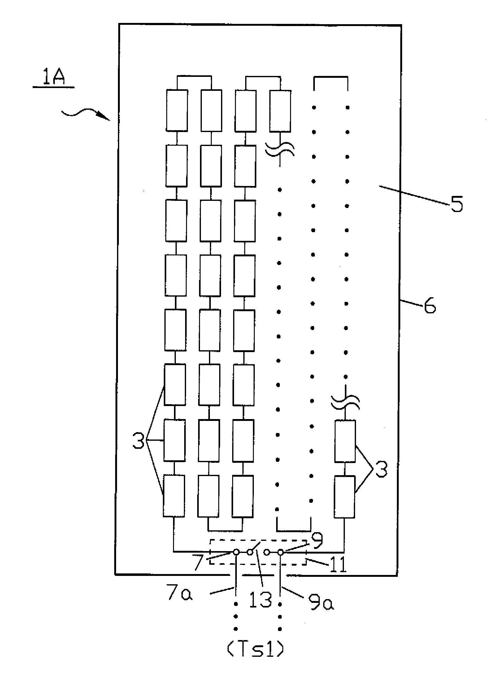
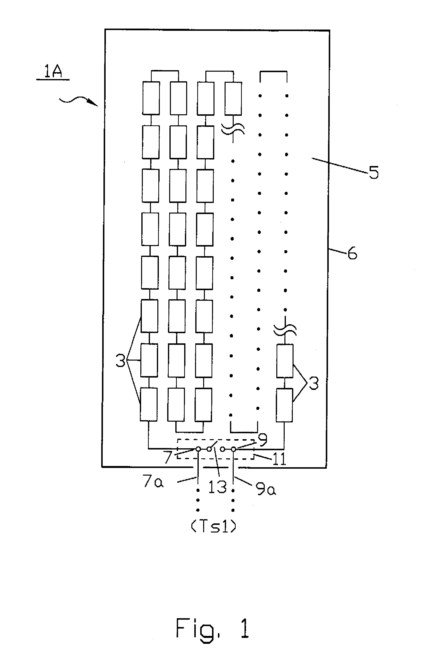
[0024] Throughout all the Figures, same or corresponding elements are generally indicated by same reference numerals. These depicted embodiments are to be understood as illustrative of the invention and not as limiting in any way. It should also be understood that the drawings are not necessarily to scale and that the embodiments are sometimes illustrated by graphic symbols, phantom lines, diagrammatic representations and fragmentary views. In certain instances, details which are not necessary for an understanding of the present invention or which render other details difficult to perceive may have been omitted.

[0025] Turning now to the drawing, and in particular to FIG. 1, there is shown a schematic illustration of a photovoltaic generator, generally designated with reference sign 1A. The generator 1A comprises a plurality of photovoltaic cells 3, which form the smallest generator unit for the conversion of sun energy into electric current. This plurality of cells 3, for example 1...


PUM


Abstract

A photovoltaic system includes a photovoltaic generator, and a thermo switch which reduces an output voltage of the photovoltaic generator in response to a trigger temperature. The photovoltaic generator may include a plurality of photovoltaic cells which are arranged in series to form a photovoltaic module. The module has ends, each of which having an electric module terminal pole, wherein the thermo switch is rendered operative in response to the trigger temperature to short-circuit the module terminal poles and to thereby reduce the output voltage generated by the photovoltaic generator.

Description

CROSS-REFERENCES TO RELATED APPLICATIONS [0001] This application claims the priority of German Patent Application, Serial No. 10 2005 017 835.9, filed Apr. 18, 2005, pursuant to 35 U.S.C. 119(a)-(d), the content(s) of which is / are incorporated herein by reference. BACKGROUND OF THE INVENTION [0002] The present invention relates, in general, to a photovoltaic generator. [0003] To ensure clarity, it is necessary to establish the definition of several important terms and expressions that will be used throughout this disclosure. The term “photo- voltaic generator” relates to any photovoltaic component which is capable to convert sun energy into an electrical current. Examples includes an individual photovoltaic cell, or an intermediate arrangement, such as, e.g. interconnection of a plurality of photovoltaic modules forming a photovoltaic string, or a complete system forming a photovoltaic device in its entirety. In the following description the term “photo-voltaic generator” may also b...

Claims


Application Information

Patent Timeline
Patent Type & Authority Applications(United States)
IPC IPC(8): H02N6/00
CPCH01L31/02021H02S99/00Y02E10/50H01L31/042
Inventor NEUSSNER, THOMAS
Owner NEUSSNER THOMAS
Why Eureka
Try Eureka