Locking assembly and method

Inactive Publication Date: 2005-03-29
HITACHI CONSTR MASCH CO LTD
View PDF7 Cites 122 Cited by
  • Summary
  • Abstract
  • Description
  • Claims
  • Application Information

AI Technical Summary

Benefits of technology

The present invention seeks to provide a locking assembly which enables a quick

Problems solved by technology

All such systems, however, generally include at least one through hole or orifice on a vertical or horizontal plane, thro

Method used


Image

  • Locking assembly and method
  • Locking assembly and method
  • Locking assembly and method

Examples


Embodiment Construction

Throughout the drawings, like numerals will be used to identify similar features, except where expressly otherwise indicated.

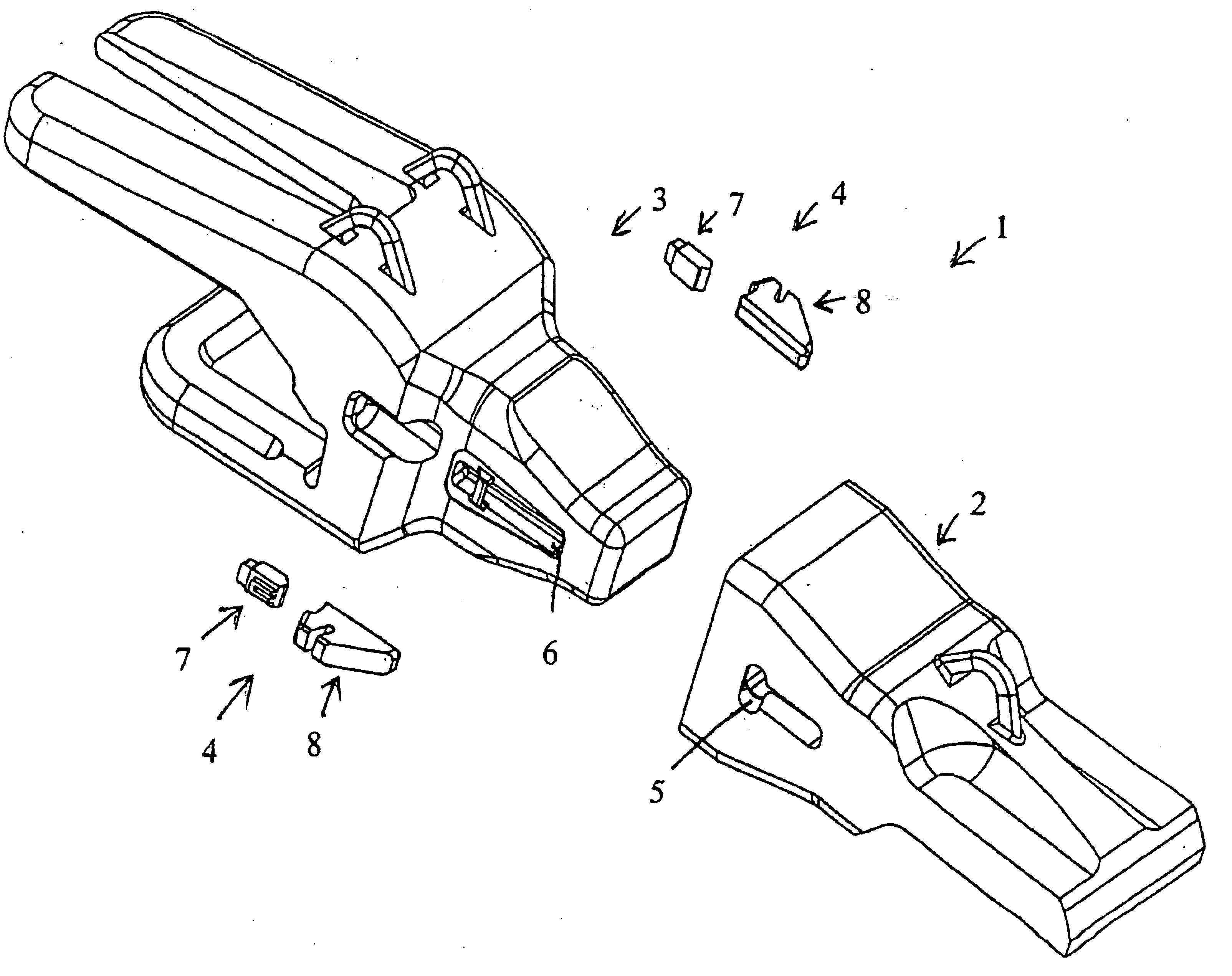
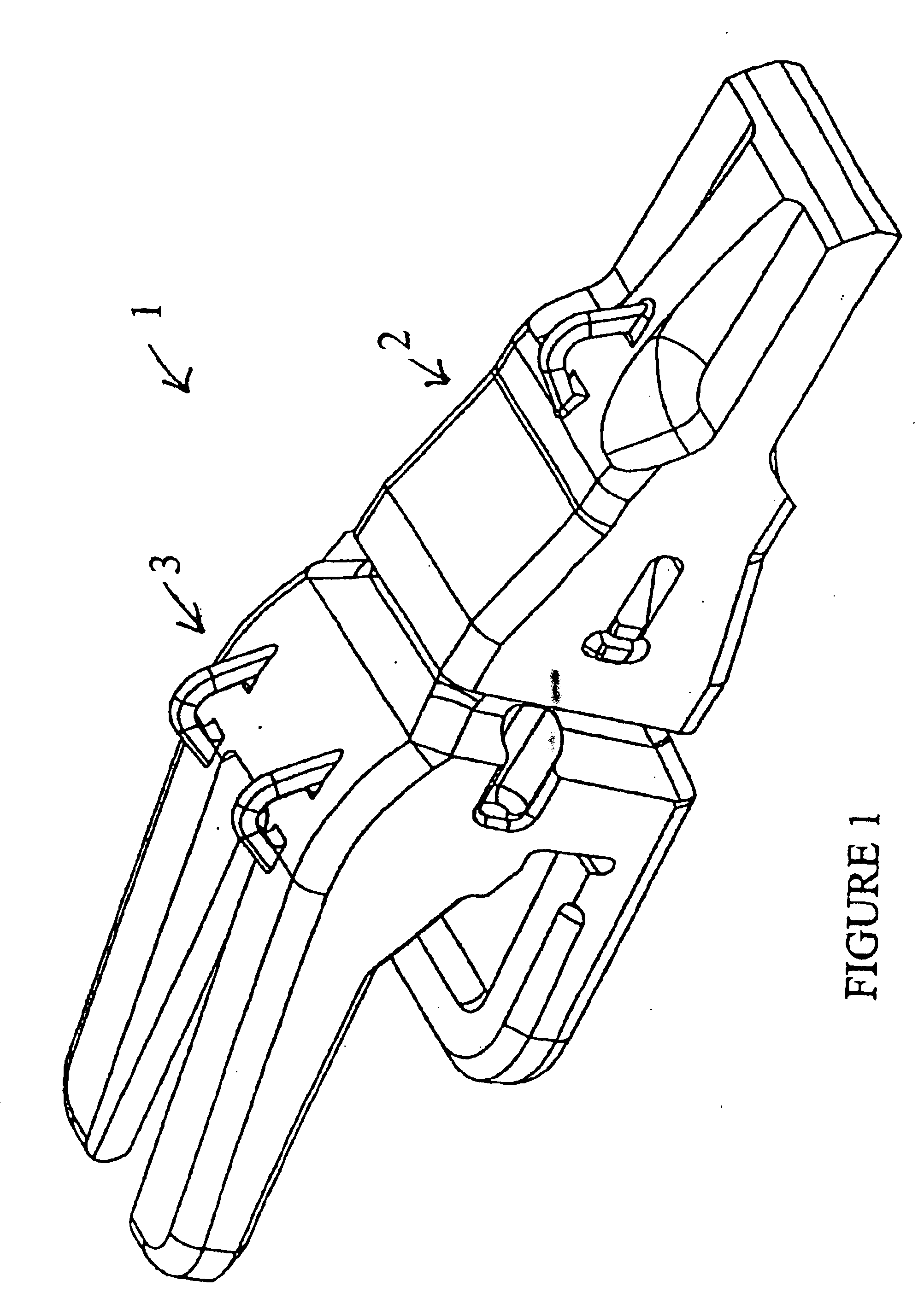
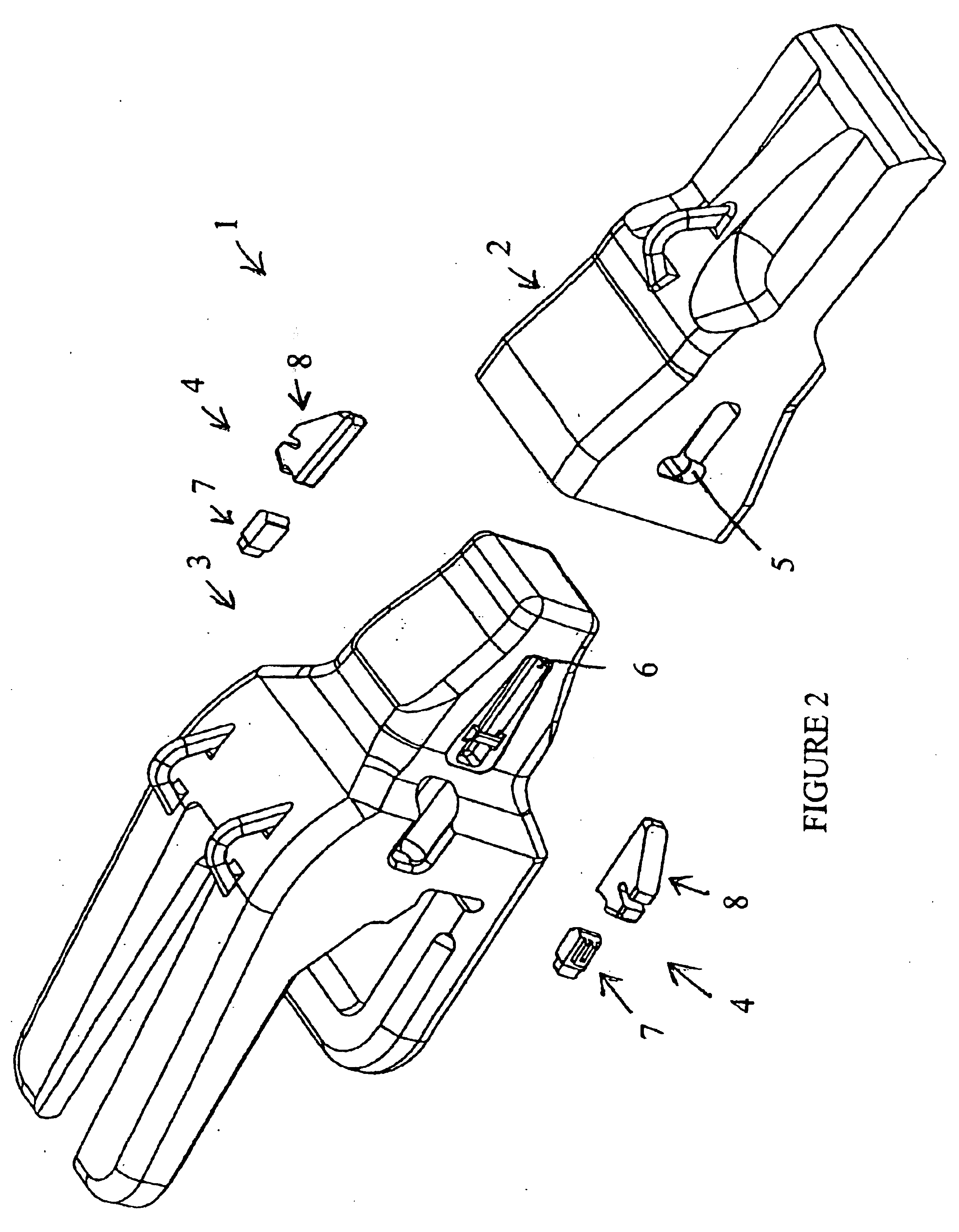
As shown in FIGS. 1 to 10 of the drawings, a locking assembly, generally designated by the numeral 1, include a wear tooth 2 adapted to be retained on a tooth adaptor 3 by means of retaining means, which generally designated by the numeral 4. As will be readily observed from the drawings, the locking assembly of this embodiment of the present invention is characterised by being provided with at least one, but preferably two, slots 5, in the or each side portions of the tooth 2, such that they cooperate with corresponding slots 6 in each side of the tooth adaptor when in the engaged position, to then receive retaining means 4.

The retaining means 4 of the present invention includes a pair of cooperating parts, a first part 7 having a shaped edge surface adapted to cooperate with a complementary shaped edge surface of second part 8. The shaped edge surface 10 of ...


PUM


Abstract

A locking arrangement (1) for releasably locking a wear tooth (2) to a tooth adaptor (3); the wear tooth (2) being defined by a top wall, a bottom wall and a pair of opposed sidewalls, each sidewall having an elongate slot (5) therethrough; the tooth adaptor (3) being of generally complementary shape to receive said wear tooth (2), and having an elongate cavity (6) on each opposed side thereof adapted to substantially align with a respective slot (5) of said wear tooth (2) when said wear tooth is installed on said tooth adaptor; said slot having a first inner surface, the locking arrangement including a retaining means (4) to be installed in each aligned cavity and slot to releasably lock said tooth (2) to said adaptor (3), the retaining means (4) including a pair of engaging retaining pieces (7, 8) adapted to fit in end-abutting relationship when in said locked position, whereby, an arcuate force is applied to at least one of said pieces (7, 8) to release said pieces from said locked position.

Description

BACKGROUND OF THE INVENTIONThe present invention relates to a locking assembly and to a method of locking a wear tooth to a tooth adaptor, typically utilised in the mining, agricultural, or other earthmoving industries.In particular, the present invention relates to a locking assembly which, by provision of a retaining means in a dual part format, various advantages are achieved.DESCRIPTION OF THE PRIOR ARTThe reference to any prior art in this specification is not, and should not be taken as, an acknowledgement or any form of suggestion that that prior art forms part of the common general knowledge in AustraliaVarious locking arrangements are presently known, for locking one or more wear tooth to it's respective tooth adaptor(s).Traditionally, such teeth are welded to the tooth adaptor such that as the tooth wears out, the old tooth is removed and replaced by a new tooth, which is welded into position.In more recent times, various methods for the removable attachment of such teeth ...

Claims


Application Information

Patent Timeline
IPC IPC(8): E02F9/28
CPCE02F9/2841E02F9/2825
Inventor KEECH, DAVID KIMHAND, ALEXANDER
Owner HITACHI CONSTR MASCH CO LTD
Why Eureka
Try Eureka