Handle cutter assembly

a cutting tool and handle technology, applied in the field of packaging tools, can solve the problems of dozens of cardboard boxes being transported, the box is much more difficult to carry, and the box is more difficult to carry

Inactive Publication Date: 2005-04-05
ROBITAILLE LIONEL L
View PDF15 Cites 20 Cited by
  • Summary
  • Abstract
  • Description
  • Claims
  • Application Information

AI Technical Summary

Benefits of technology

The cutting edge may be adapted to form a C-shaped cut between a start point and an end point. The cut is sized such that handles can be formed when the cutting edge is applied

Problems solved by technology

As a result, the box is much more difficult to carry when the boxes are individually transported.
If the box is reused later, for moving, storage etc., the lack of a handle in the cardboard will make carrying the box more difficult.
Move

Method used


Image

  • Handle cutter assembly
  • Handle cutter assembly
  • Handle cutter assembly

Examples


Embodiment Construction

The novel features which are believed to be characteristic of the present invention, as to its structure, organization, use and method of operation, together with further objectives and advantages thereof, will be better understood from the following discussion.

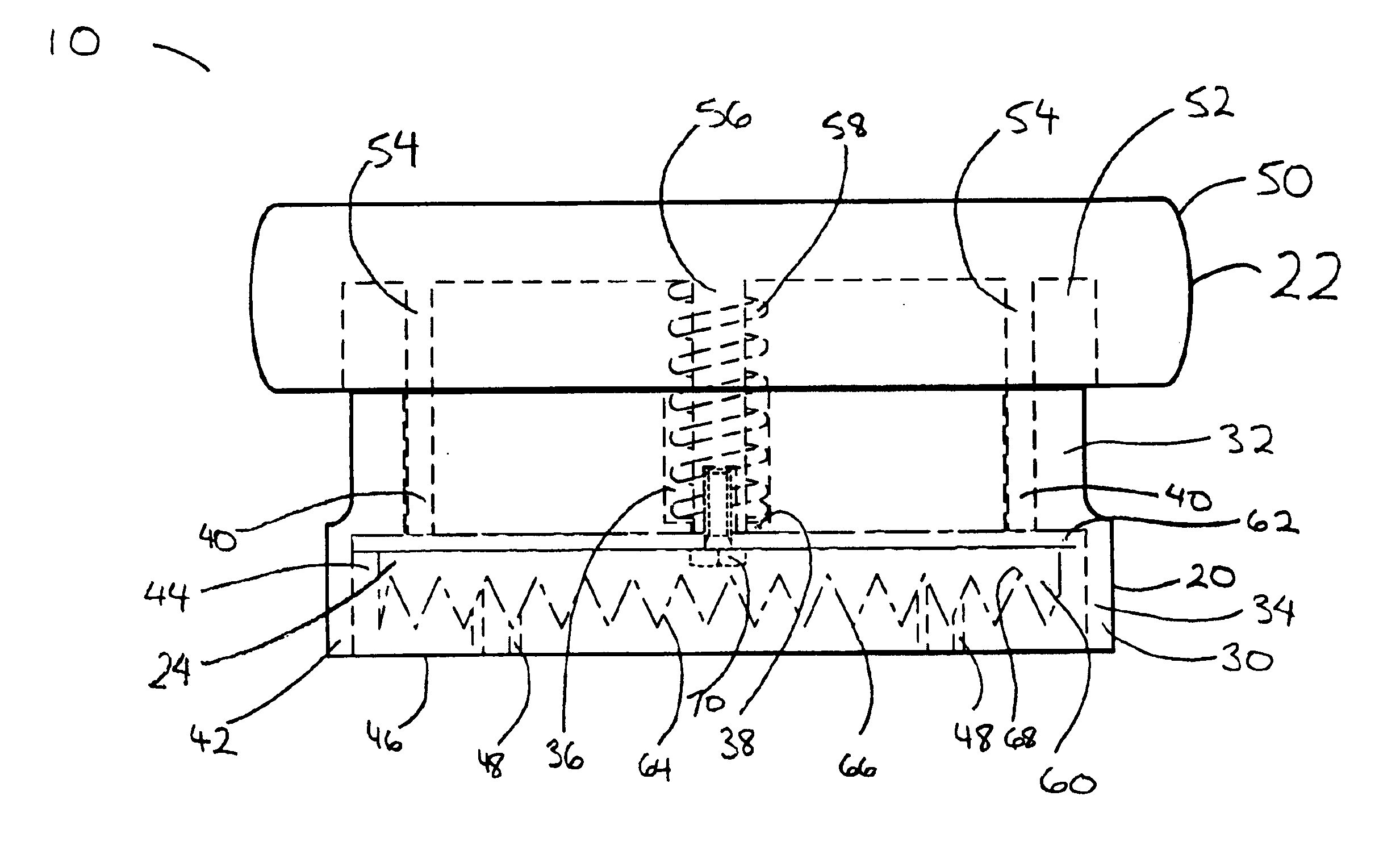
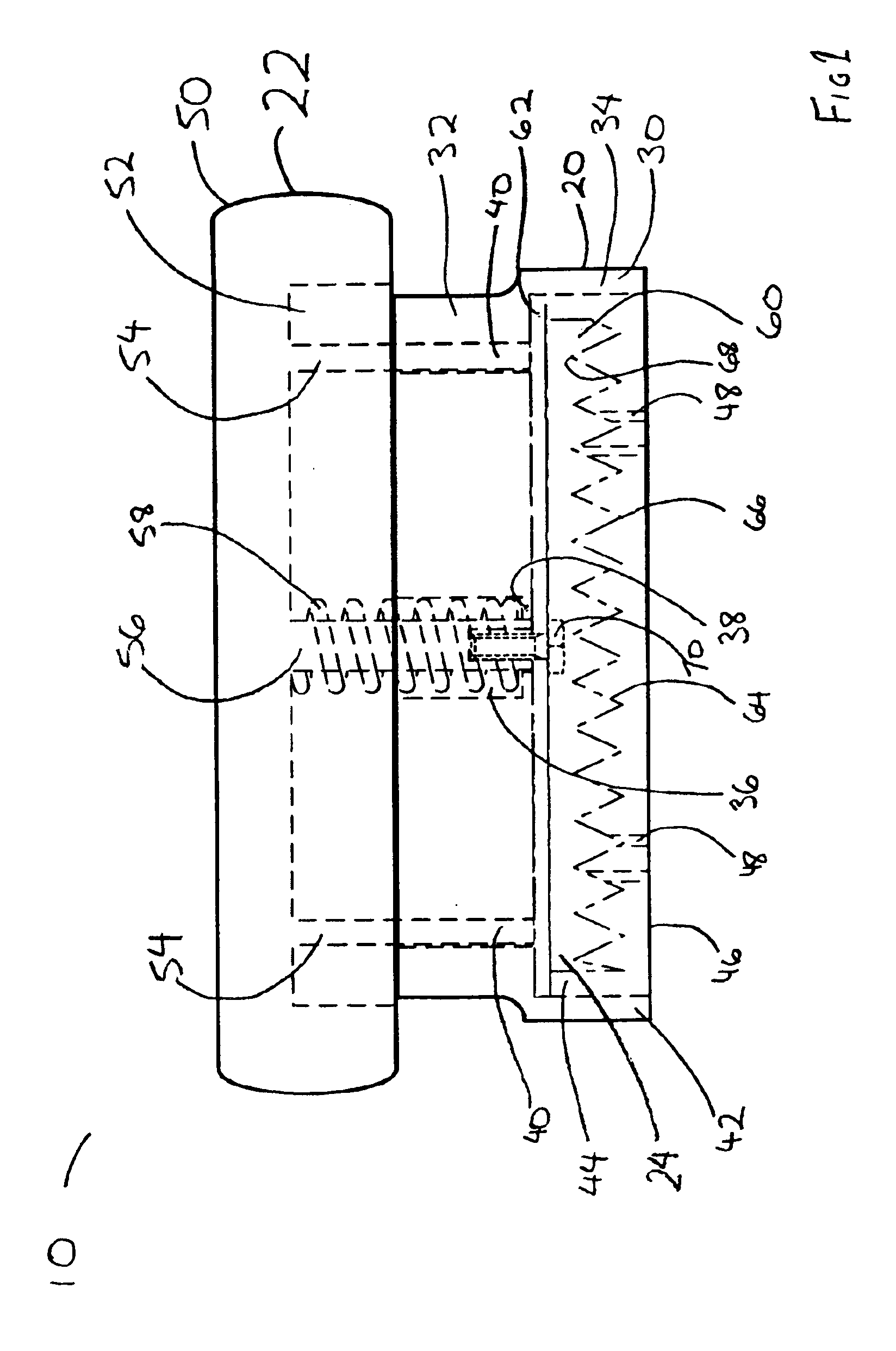
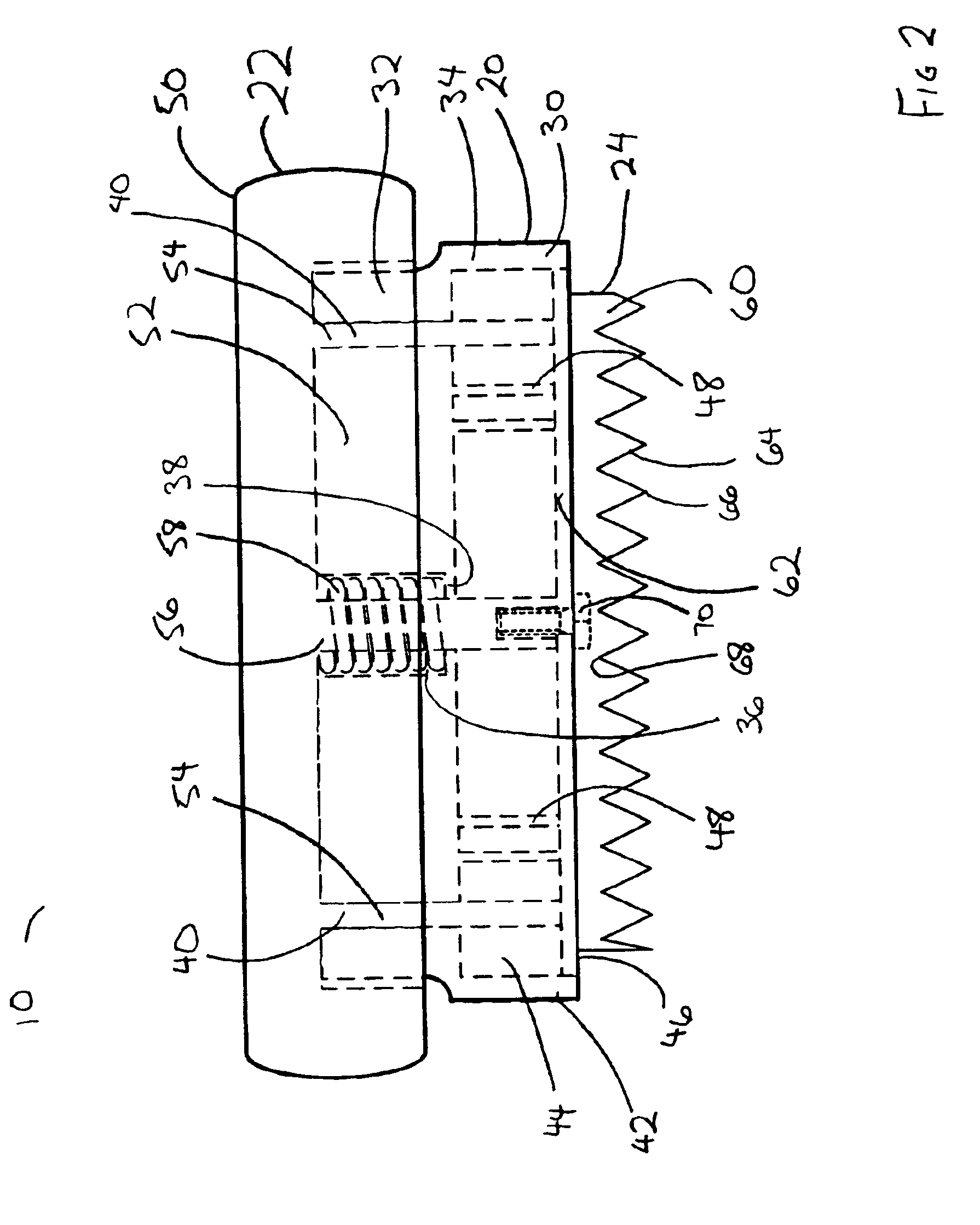
FIGS. 1 through 8 show a handle cutter assembly 10 in accordance with present invention. Handle cutter assembly 10 is made up of a body 20, a grip portion 22 slidably mounted to body 20, a blade assembly 24 affixed to grip portion 22 and a base guide 26.

Body 20 is cylindrical body having a variable cross-section. Body 20 has an outer shell 30 surrounding an upper end or portion 32 and a lower end or portion 34. Upper portion 32 preferably has a smaller cross-sectional area than lower portion 34. Upper portion 32, as shown in FIG. 5, has a generally solid interior. However, upper portion 32 is provided with a blade connector aperture 36. Blade connector aperture 36 is a downwardly extending cylindrical aperture which us centra...


PUM


Abstract

A handle cutter assembly for making C-shaped handle cuts in cardboard boxed and the like. The cutter assembly has a body having an outer shell defining a blade cavity therein. The body has an upper end and a lower end. A lower aperture is positioned in the lower end. The body also has a blade slider mounted thereto and a grip portion is mounted to its upper end. A cutting blade is mounted within the blade cavity. The cutting blade is slidable by the blade slider between a retracted position substantially within the blade cavity and a cutting position. In the cutting position, the cutting blade extends below the lower end through the lower aperture. The cutting blade has a cutting edge extending away from the body which has a C-shaped cutting profile.

Description

FIELD OF THE INVENTIONThe present invention relates to the art of packaging tools used in the packaging and shipping of items in cardboard boxes and the like and more particularly pertains to a new handle cutter assembly for the purpose of cutting handle holes into a cardboard box.BACKGROUNDCardboard boxes are used in the shipping and storage of a wide variety of products. Cardboard boxes are convenient, relatively durable, reusable and recyclable. There are many cardboard boxes in use for household storage which were originally used to ship other goods.Very often cardboard boxes are used for the storage and transport of very heavy products or other objects. In such situations, the manufacturer of the heavy product may order cardboard boxes with specially formed handles on each side of the box for the purposes of grasping and lifting the box. The handles are formed by making C-shaped cuts in the side of the box. The cardboard lying inside the “C” can be pushed inwards and folded alo...

Claims


Application Information

Patent Timeline
IPC IPC(8): B26F1/44B26F1/00B26F1/32B26F1/22B26F1/38
CPCB26F1/22B26F1/44B26F1/32
Inventor ROBITAILLE, LIONEL L.
Owner ROBITAILLE LIONEL L
Why Eureka
Try Eureka