Tapered coupling
a tapered coupling and coupling technology, applied in the field of tapered couplings, can solve the problems of unsatisfactory rotational play or backlash, undesirable wear and damage to shafts and couplings, and undesirable increase in production costs
- Summary
- Abstract
- Description
- Claims
- Application Information
AI Technical Summary
Benefits of technology
Problems solved by technology
Method used
Image

Examples
second embodiment
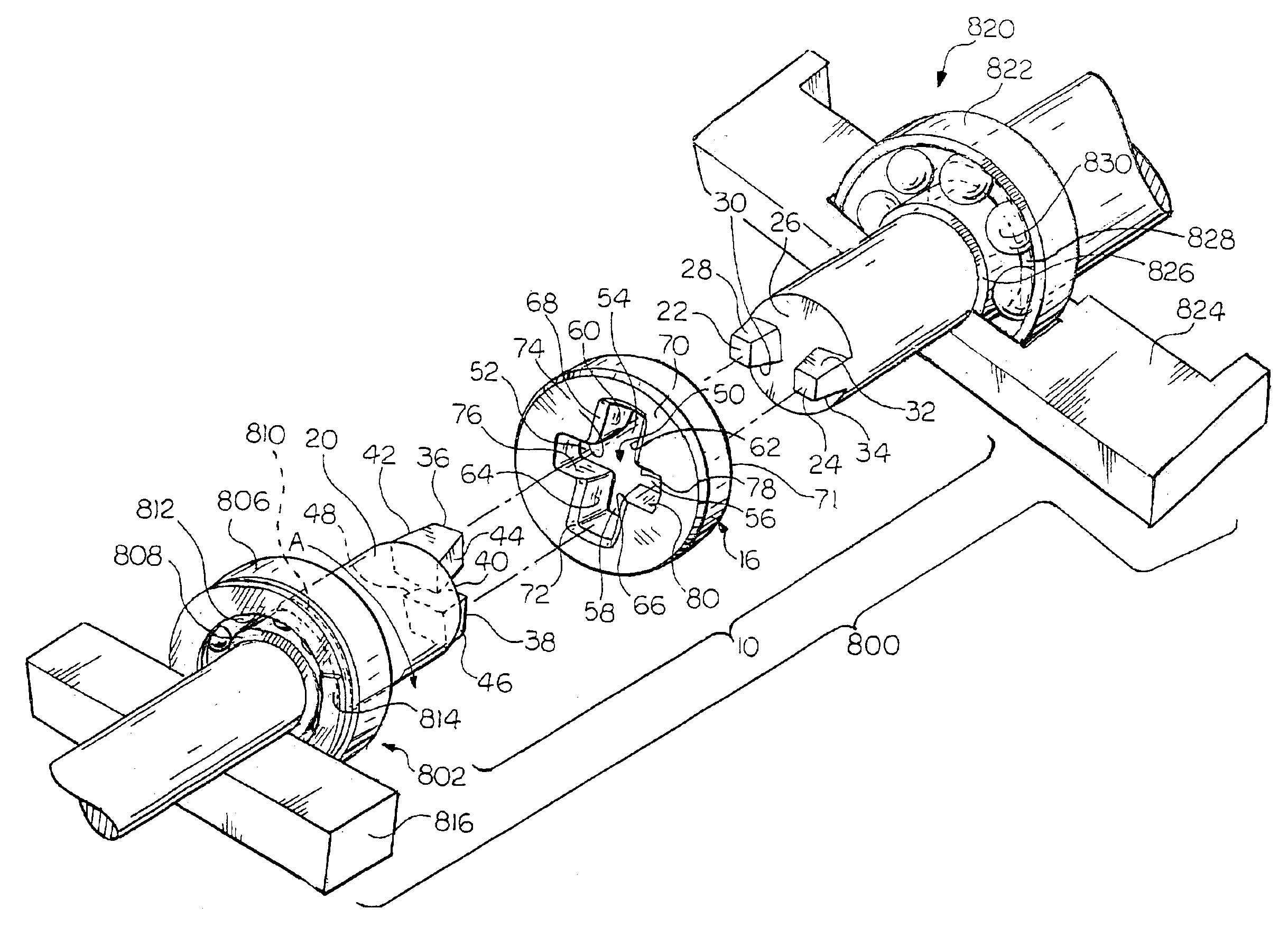
Referring now to FIG. 18, there is shown a shaft and bearing system 800. The shaft and bearing system 800 includes a shaft coupling assembly 10 as illustrated in FIG. 1 and previously described herein. A preloaded bearing 802 is disposed on the driven shaft 14 which permits movement of the bearing 802 in a direction along the axis of the driven shaft 14. The bearing 802 includes an outer race 806 and an inner race 808. The inner race 808 of the bearing 802 abuts a step 810 formed in an outer surface of the driven shaft 14. A plurality of balls 812 is disposed between the inner race 808 and the outer race 806 of the bearing 802 to permit rotational movement therebetween. A spring 814 abuts the outer race 806 of the bearing 802 to urge the bearing 802 and the driven shaft 14 towards engagement with the coupling main body 16 and the driving shaft 12. The spring 814 also abuts and is held in place by a wall or restricting frame 816. The inner race 808 abuts the step 810 on the driven sh...
third embodiment
Referring now to FIG. 5, there is shown a shaft coupling assembly 140. The shaft coupling assembly 140 includes a driving shaft 142, a driven shaft 144, and a coupling main body 146. A direction of rotation ‘C’ is shown for both the driving shaft 142 and the driven shaft 144. A first end 148 of the driving shaft 142 is drivingly engaged with a prime mover (not shown) such as a motor, for example. A first end 150 of the driven shaft 144 is drivingly engaged with a rotatable machine (not shown) such as a pump or compressor, for example. It is understood that the rotation direction and drive versus driven load can be interchanged at any time.
A pair of diametrically opposed tabs 152, 154 extend axially outwardly from a second end 156 of the driving shaft 142. A pair of diametrically opposed tabs 158, 160 extend axially outwardly from a second end 162 of the driven shaft 144. A spring plate 164 is disposed between the driven shaft 144 and the coupling main body 146. In the illustrated em...
fourth embodiment
Referring now to FIG. 6, there is shown a shaft coupling assembly 200. The shaft coupling assembly 200 includes a driving shaft 202, a driven shaft 204, and a coupling main body 206. A direction of rotation ‘D’ is shown for both the driving shaft 202 and the driven shaft 204. A first end 208 of the driving shaft 202 is drivingly engaged with a prime mover (not shown) such as a motor, for example. A first end 210 of the driven shaft 204 is drivingly engaged with a rotatable machine (not shown) such as a pump or compressor, for example. It is understood that the rotation direction and drive versus driven load can be interchanged at any time.
A pair of diametrically opposed tabs 212, 214 extend axially outwardly from a second end 216 of the driving shaft 202. A pair of diametrically opposed tabs 218, 220 extend axially outwardly from a second end 222 of the driven shaft 204. A spring plate 224 is disposed between the driving shaft 202 and the coupling main body 206. An aperture 226 is f...
PUM
 Abstract
Description
Claims
Application Information
 - R&D Engineer
- R&D Manager
- IP Professional
- Industry Leading Data Capabilities
- Powerful AI technology
- Patent DNA Extraction
Browse by: Latest US Patents, China's latest patents, Technical Efficacy Thesaurus, Application Domain, Technology Topic.
© 2024 PatSnap. All rights reserved.Legal|Privacy policy|Modern Slavery Act Transparency Statement|Sitemap