

Optical transmission system
a transmission system and optical transmission technology, applied in the field of optical transmission systems, can solve the problems of 65 ps/nm residual dispersion, difficult to significantly lower this value in quartz-based optical fibers, and significant deterioration of transmission characteristics, so as to achieve low residual dispersion, maintain yield, and reduce residual dispersion
- Summary
- Abstract
- Description
- Claims
- Application Information
AI Technical Summary
Benefits of technology
Problems solved by technology
Method used
Image

Examples
example 1
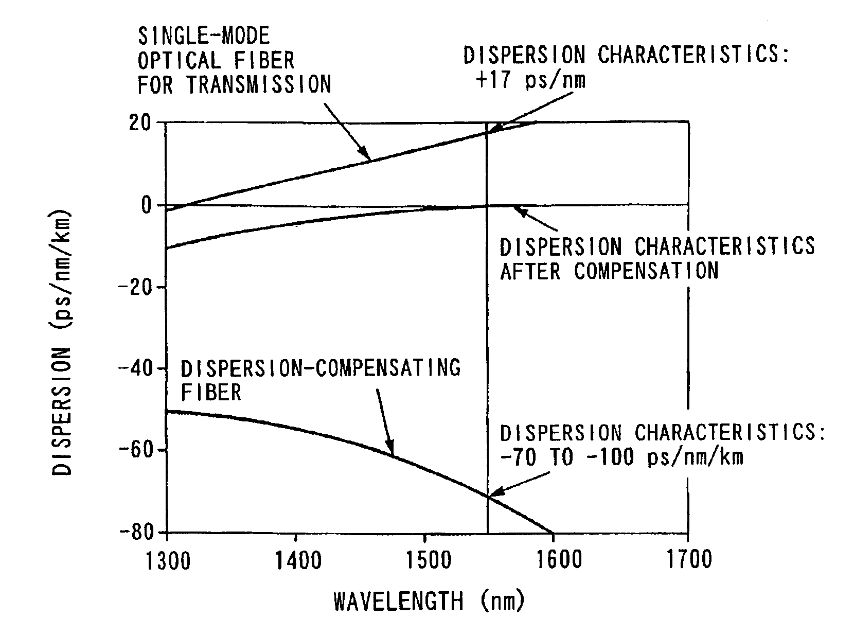
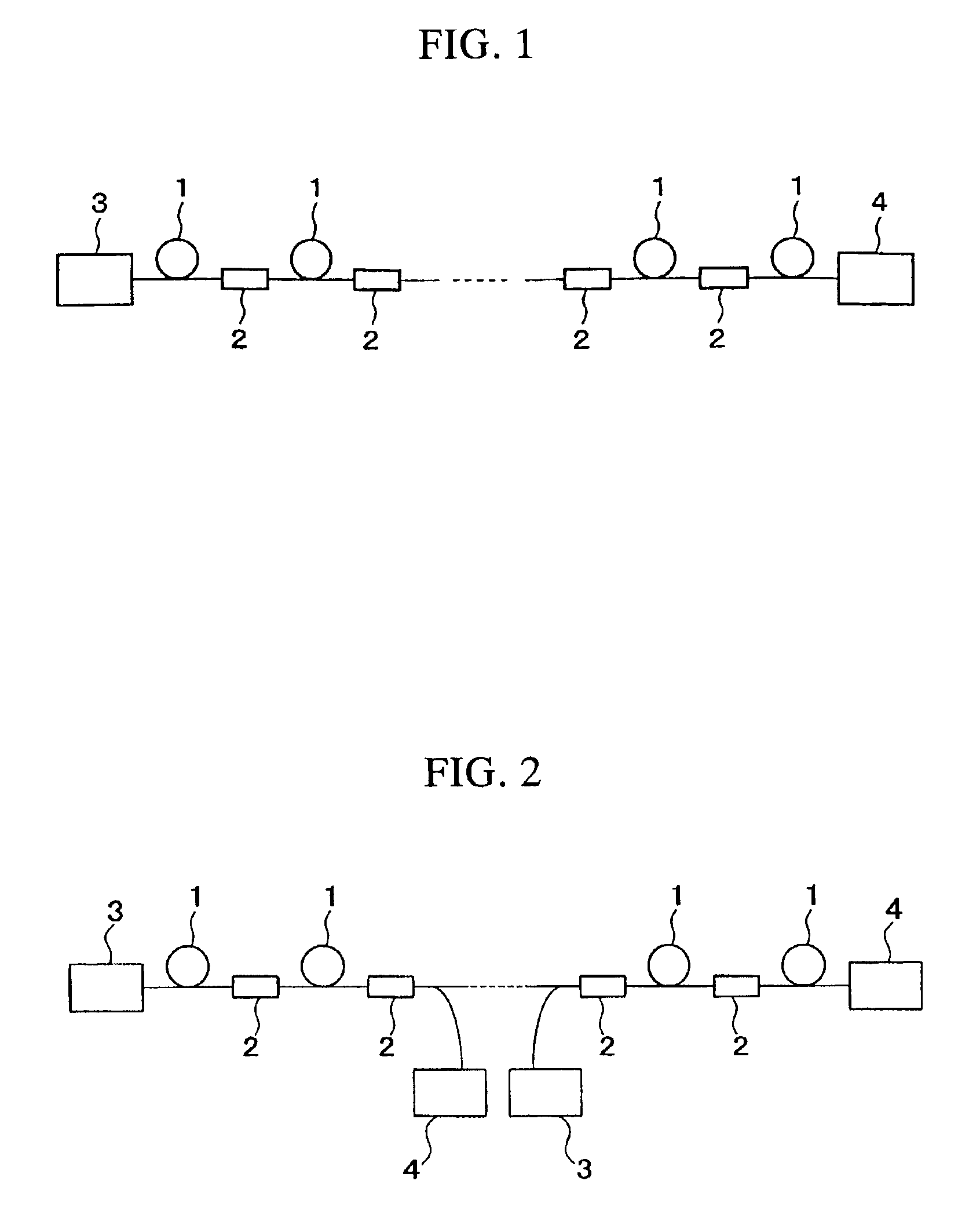
[0080]A dispersion compensating fiber having negative wavelength dispersion and negative dispersion slope was inserted into a single-mode optical fiber for transmission having positive wavelength dispersion and positive dispersion slope every 80 km to compensate wavelength dispersion of the optical transmission path over a wide wavelength range. The operating wavelength range here was 1530-1570 nm, and dispersion compensation was performed at 1550 nm corresponding to the central wavelength of this operating wavelength range.
[0081]The dispersion characteristics at each wavelength of the single-mode optical fiber are 15.8 ps / nm / km at 1530 nm, 17.0 ps / nm / km at 1550 nm, and 18.2 ps / nm / km at 1570 nm. In addition, as shown in Table 1, the dispersion compensating fiber used in each span had a residual dispersion error at the central wavelength of ±3.0% or less, the dispersion slope compensation ratio was within 100±30%, it satisfied equation (1) in each span, and the dispersion compensatio...
example 2
[0084]A dispersion compensating fiber having negative wavelength dispersion and negative dispersion slope was inserted into a single-mode optical fiber for transmission having positive wavelength dispersion and positive dispersion slope every 80 km to compensate wavelength dispersion of the optical transmission path over a wide range. The operating wavelength range here was 1530-1570 nm, and dispersion compensation was performed at 1550 nm corresponding to the central wavelength of this operating wavelength range.
[0085]The dispersion characteristics at each wavelength of the single-mode optical fiber are 15.8 ps / nm / km at 1530 nm, 17.0 ps / nm / km at 1550 nm, and 18.2 ps / nm / km at 1570 nm. In addition, as shown in Table 2, the dispersion compensating fiber used in each span had a residual dispersion error at the central wavelength of ±3.0% or less, the dispersion slope compensation ratio was within 100±30%, it satisfied equation (1) in each span, and the dispersion compensation condition...
example 3
[0089]A dispersion compensating fiber having negative wavelength dispersion and negative dispersion slope was inserted into a single-mode optical fiber for transmission having positive wavelength dispersion and positive dispersion slope every 80 km to compensate wavelength dispersion of the optical transmission path. The operating wavelength range here was 1530-1570 nm, and dispersion compensation was performed at 1550 nm corresponding to the central wavelength of this operating wavelength range.
[0090]The dispersion characteristics at each wavelength of the single-mode optical fiber are +3.6 ps / nm / km at 1530 nm, +4.5 ps / nm / km at 1550 nm, and +5.4 ps / nm / km at 1570 nm. In addition, as shown in Table 3, the dispersion compensating fiber used in each span had a residual dispersion error at the central wavelength of ±3.0% or less, the dispersion slope compensation ratio was within 100±30%, it satisfied equation (1) in each span, and the dispersion compensation conditions were set compara...
PUM
 Abstract
Description
Claims
Application Information