Shelf and display device

Inactive Publication Date: 2005-04-12
NDR
View PDF29 Cites 31 Cited by
  • Summary
  • Abstract
  • Description
  • Claims
  • Application Information

AI Technical Summary

Problems solved by technology

Such rotation results in the product not being presented correctly at the dispensing end of the display device.
However, with such displays there is often insufficient pressure acting on the last unit loaded in the display that one or more of the units fail to advance to the correct presentation position at the dispensing location of the display.
These devices also have the disadvantage that the modular unit frequently gets stuck in the display device.

Method used


Image

  • Shelf and display device
  • Shelf and display device
  • Shelf and display device

Examples


Embodiment Construction

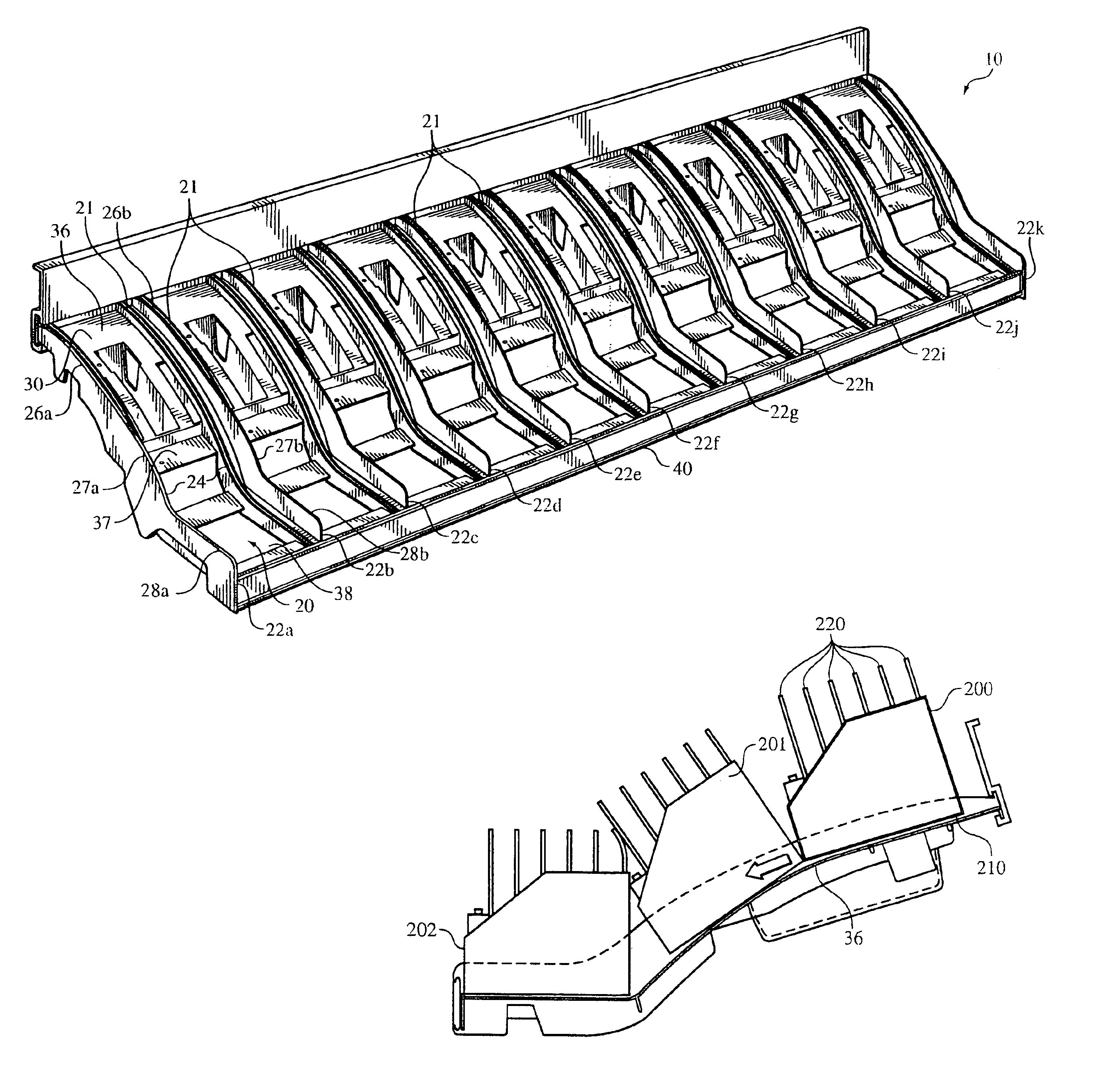
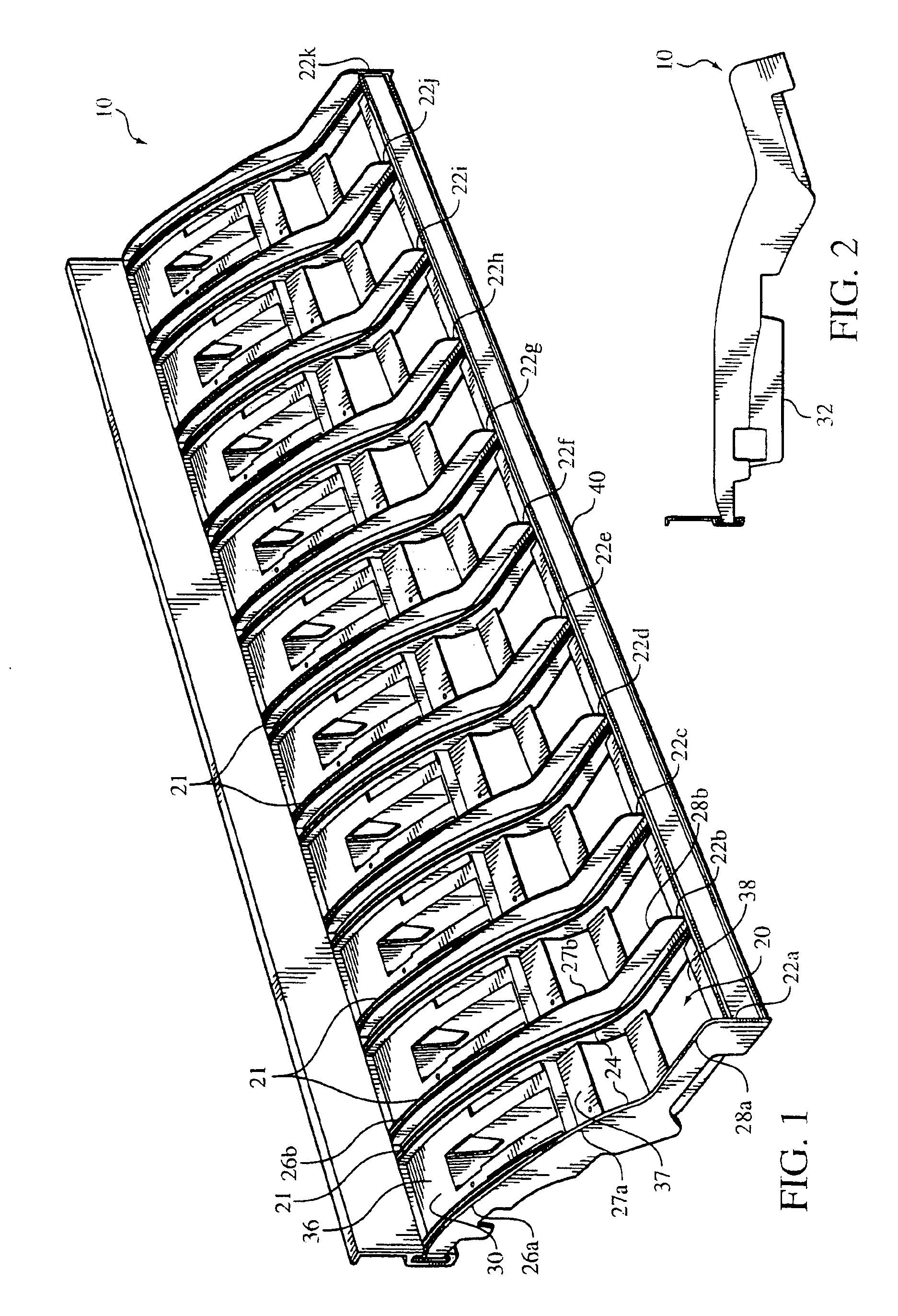
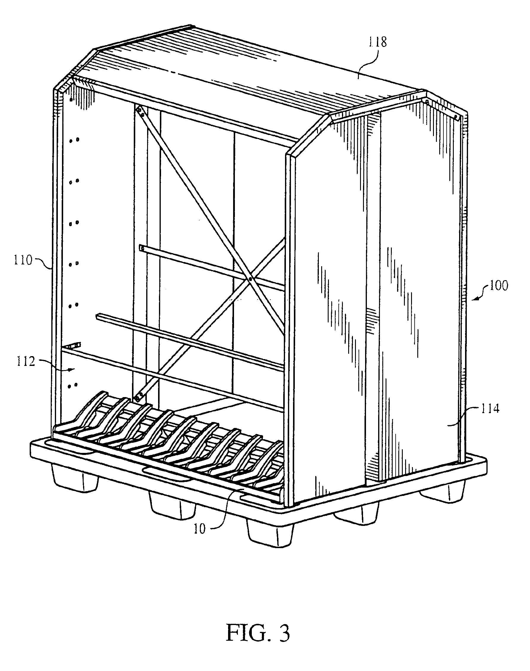
Turning now to the drawings, FIGS. 1-2 show a shelf 10 for a display device such as display device 100 shown in FIGS. 3-4. Shelf 10 is designed to hold at least one modular merchandise unit such as battery package carrier 200 shown in FIG. 4. As shown in FIG. 4, each modular merchandise preferably is presented to the consumer in a substantially upright or perpendicular position. As shown in FIGS. 5A-5D modular merchandise unit 200 has a substantially flat base 210 and holds a number of merchandise packages 220, six being shown for each unit in FIGS. 5A-5D.

Shelf 10 has a track 20 formed by two spaced walls 22a, 22b defining a channel 24 between walls 22a, 22b. Preferably, shelf 10 has a number of adjacently-spaced walls defining at least two channels. For example, as shown in FIG. 1, shelf 10 may have additional tracks formed by walls 22b, 22c; 22c, 22d; 22d, 22e; 22e, 22f; 22f, 22g; 22g, 22h; 22h, 22i; 22i, 22j; 22j, 22k. In the embodiment shown in FIG. 1, walls 22a and 22k are oute...


PUM


Abstract

A display device has at least one shelf for modular merchandise units having a substantially flat base. The shelf has at least two spaced walls defining a channel between the walls. At least one support is disposed in the channel and receives the base of the merchandise unit or units. Each support has a rearward portion elevated at a first angle, a substantially horizontal forward portion, and an intermediate portion elevated at a second angle greater than the first angle and connecting the rearward and forward portions. When placed on the rearward portion of the support, the merchandise unit will descend by gravity to the forward portion of the support for access to the unit in a selected presentation position.

Description

BACKGROUND OF THE INVENTION1. Field of the InventionThe present invention relates to display devices and more particularly to a shelf for a display device designed to hold modular merchandise units such as packet boxes and to provide a gravity feed for the product so that when a box is removed, the next box will slide down for access by a consumer.2. The Prior ArtAt the present time there are a large variety of known display devices in which articles of merchandise are loaded at one side of the device and move by gravity along a downward course to a forward or dispensing position at the opposite side of the device. See U.S. Pat. No. 4,744,489 to Binder et al. ; U.S. Pat. No. 3,404,927 to Mellion; U.S. Pat. No. 3,900,112 to Azzi et al.; U.S. Pat. No. 1,317,534 to Williams; U.S. Pat. No. 1,711,329 to Short; U.S. Pat. No. 2,649,207 to Shield; U.S. Pat. No. 3,019,907 to Belejack; and U.S. Pat. No. 5,353,939 to Beeler et al.The Binder et al. has two straight parallel courses and has a no...

Claims


Application Information

Patent Timeline
IPC IPC(8): A47F5/00A47B96/02A47F1/04A47F1/12A47F3/00A47F3/14G09G
CPCA47F5/0018A47F1/12
Inventor MASON, TIMOTHY L.
Owner NDR
Why Eureka
Try Eureka