
User interface for controlling a whirlpool tub

a whirlpool tub and user interface technology, applied in the field of whirlpool control systems and user interface devices, can solve problems such as the need for a complex user control panel

Active Publication Date: 2005-04-12
KOHLER CO
View PDF12 Cites 36 Cited by
  • Summary
  • Abstract
  • Description
  • Claims
  • Application Information

AI Technical Summary

Benefits of technology

A controller is connected to the plurality of sensors and determines motion of the dial in response to the output signals from the plurality of sensors. In a preferred embodiment of the user interface, the controller determines when the dial has moved a given amount and the direction of that movement. The controller employs that determination in selecting a function of the plumbing equipment to be controlled. The preferred user interface also has other input devices by which the user defines operational characteristics of the selected function. Indicators of selection of a particular function and the magnitude of an operational characteristic of the selected function are provided to the user. Thus the functions can be controlled independently by means of this user interface.

Problems solved by technology

Heretofore, this required a complex user control panel.

Method used


Image

  • User interface for controlling a whirlpool tub
  • User interface for controlling a whirlpool tub
  • User interface for controlling a whirlpool tub

Examples


Embodiment Construction

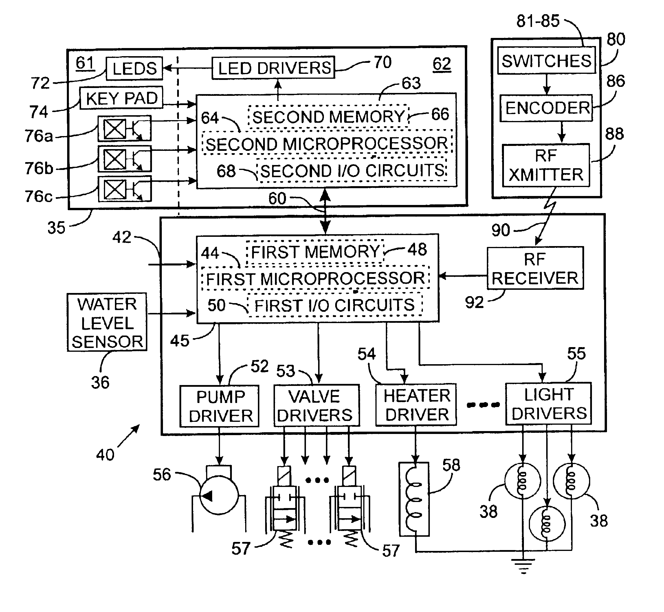
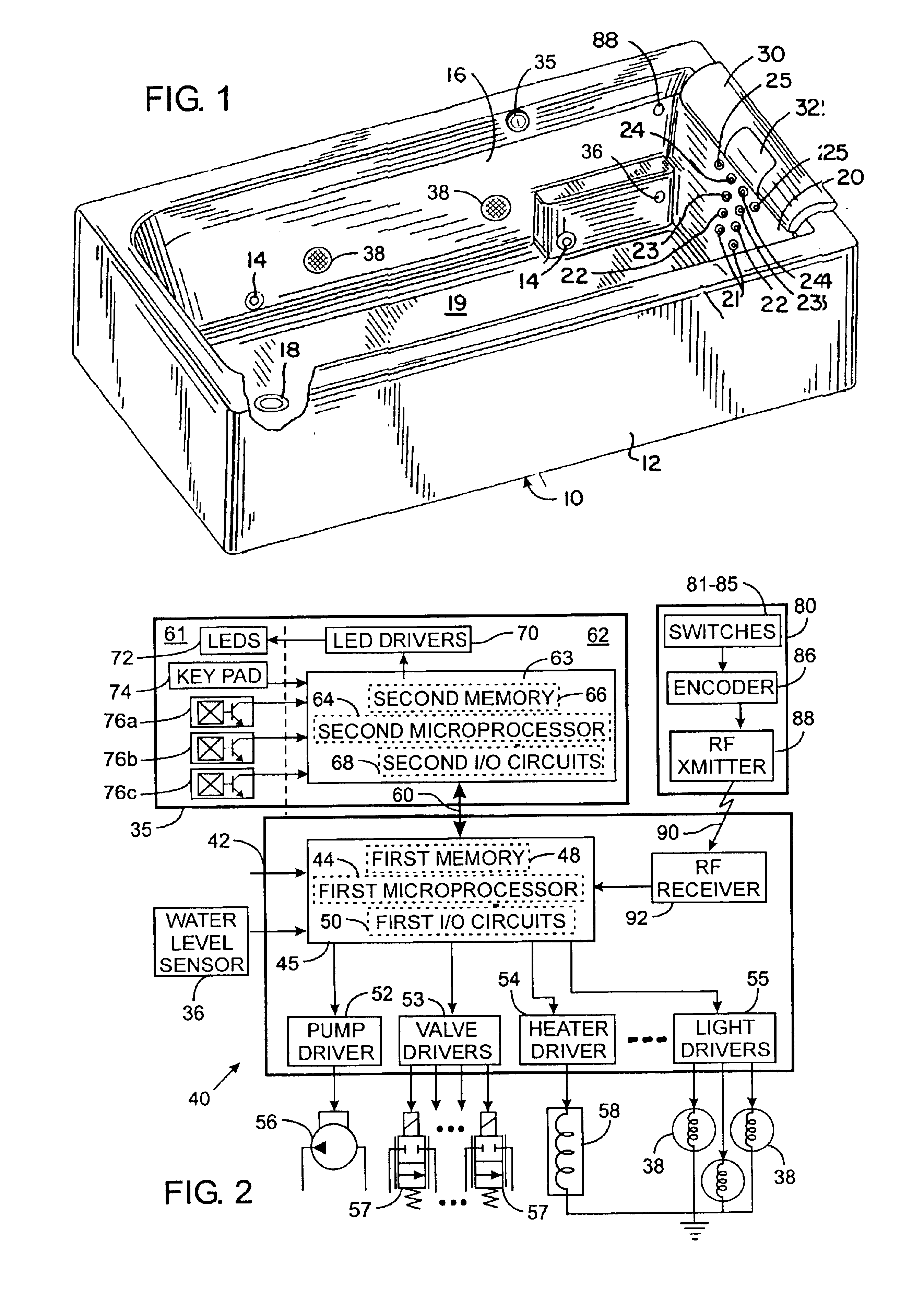
With reference to FIG. 1, a hydro-massage whirlpool 10 includes a tub 12 having a plurality of conventional whirlpool nozzles 14 projecting through an interior side wall 16. The tub floor 19 has a standard drain opening 18. One end of the tub 12 has an end wall 20 with a plurality of nozzles 21, 22, 23, 24 and 25 that are arranged in pairs. Four of the pairs 21, 22, 23 and 24 are stacked above one another with the fifth pair of nozzles 25 located horizontally on either side of the fourth pair of nozzles 24. The flow of water through each pair of nozzles 21-25 is controlled by a separate valve so that its flow may be regulated independently of the other pairs of nozzles.

A soft cushion 30 is attached to the rim of the tub at the one end 20. The cushion 30 is formed of an outer covering of a vinyl material with a soft filler inside. The cushion 30 has a central cut out section in which a separate removable pillow 32 is located. The pillow 32 has a U-shaped inner pad of resilient materi...


PUM


Abstract

An apparatus is provided to control a plumbing fixture, such as a whirlpool, that has electrically operated components. The apparatus has a dial that is moveable by the user into a plurality of positions to select a function of the plumbing fixture to be controlled. A unique sensor arrangement detects motion and the direction of the motion and provides a signal to a controller that changes the valve of a pointer that designates which function is presently selected. The user then presses a keypad to indicate whether the selected function is to be activated or deactivated and to control the intensity of the selected function. The signals from the keypad also are applied to the controller.

Description

CROSS-REFERENCE TO RELATED APPLICATIONSNot ApplicableSTATEMENT REGARDING FEDERALLY SPONSORED RESEARCH OR DEVELOPMENTNot ApplicableBACKGROUND OF THE INVENTION1. Field of the InventionThe present invention relates to plumbing equipment, such as spas and whirlpool tubs, and more particularly to electrical control systems for operating components of the spa or whirlpool tub, and specifically to user interface devices for the whirlpool control system.2. Description of the Related ArtHydro-massage spas and whirlpool tubs provide a therapeutic massaging action by delivering water through several nozzles in the tub walls to create a circulating flow of turbulent water. The tub water is drawn through a drain to a pump and then is forced outward through the nozzles to create jets of water in the tub. Air can be added to the circulating water at a controlled rate at each nozzle to increase the turbulence and massaging action of the water exiting the nozzle. Often each nozzle can be pivoted to ...

Claims


Application Information

Patent Timeline
IPC IPC(8): G05B19/10G05B19/04
CPCA61H33/005G01D5/145G05B19/106H03K17/97A61H2033/007H03K2217/94068H01H25/041H01H2025/045H01H2239/024G05B2219/23035
Inventor MUELLER, CARL F.TEMPAS, JEFFREY F.SWART, PETER W.THOMAS, CARTER J.BAUER, RONALD A.
Owner KOHLER CO
Learn More