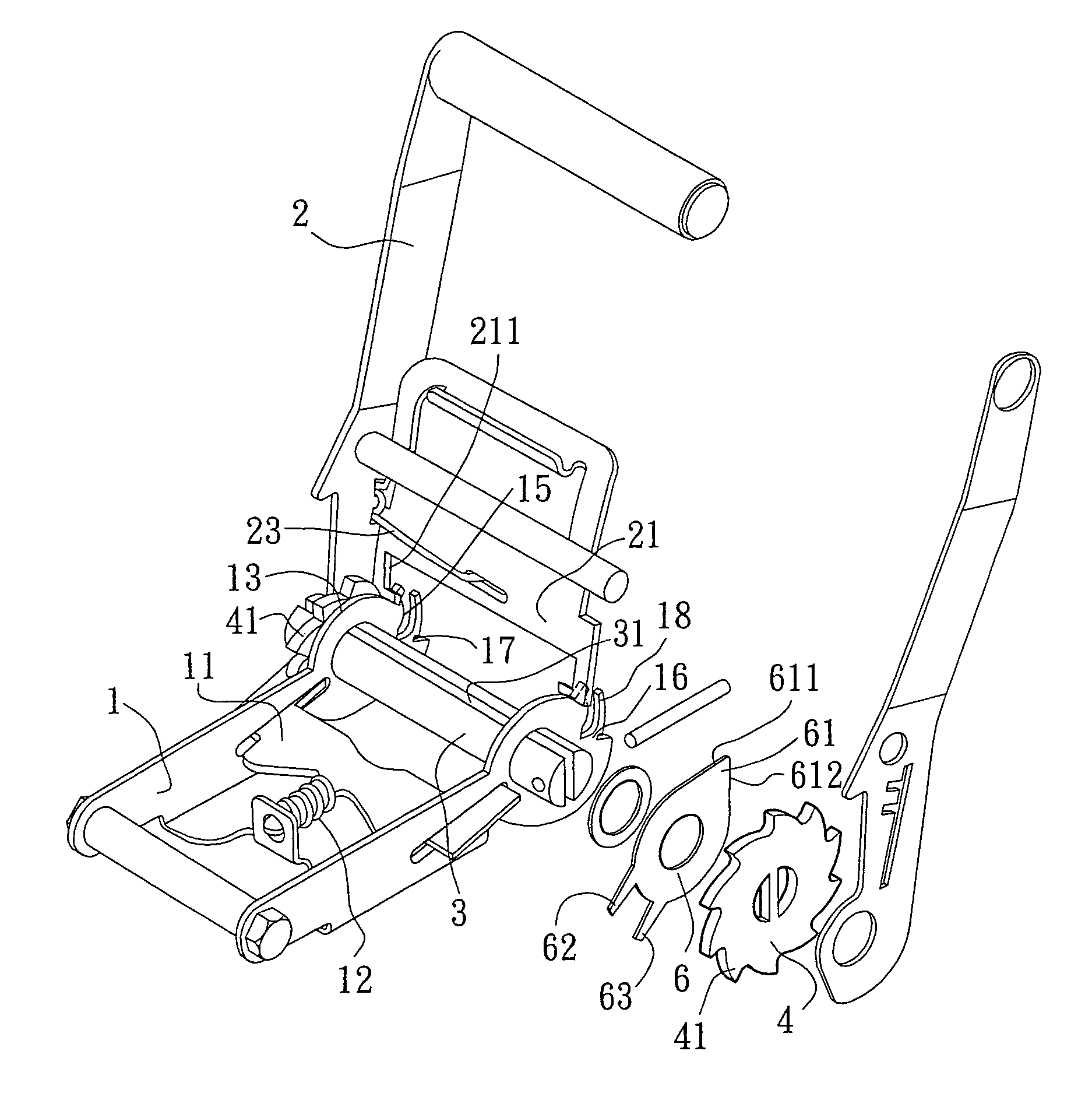
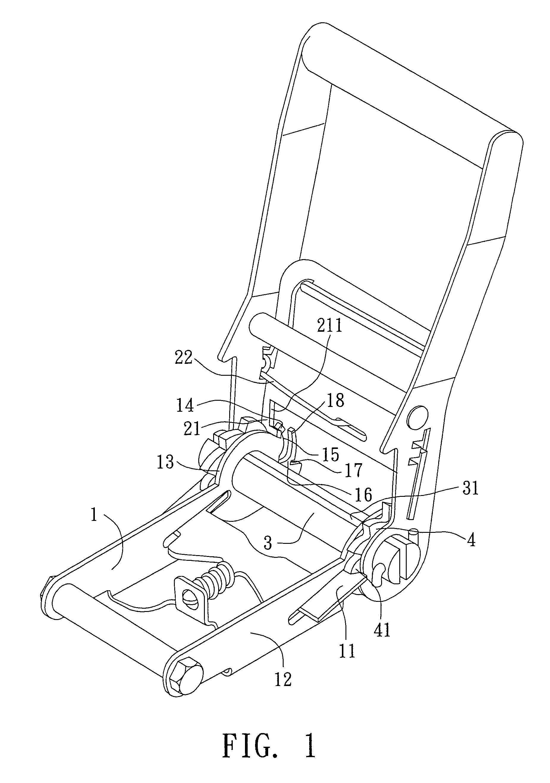
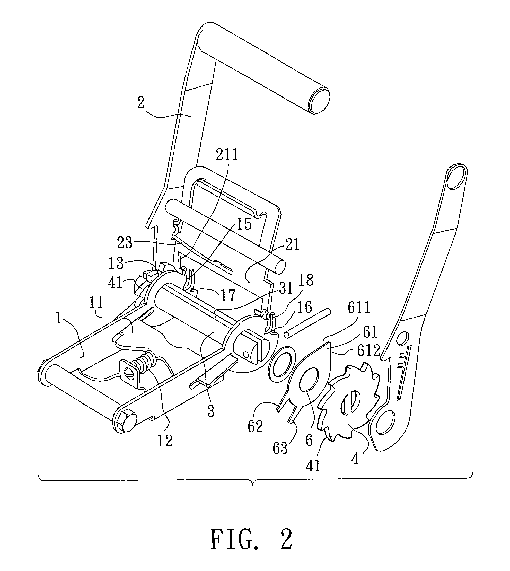
Belt reel assembly for fastening goods on a truck

a technology for belts and trucks, applied in the field of belts, can solve the problems of laborious design and inconvenient operation, and achieve the effect of releasing the strain of belts

Active Publication Date: 2005-04-19
RATCHET
View PDF4 Cites 39 Cited by
  • Summary
  • Abstract
  • Description
  • Claims
  • Application Information

AI Technical Summary

Benefits of technology

[0008]The main objective of the present invention is to provide an improved belt reel for fastening good...

Problems solved by technology

It is a laborious desi...

Method used


Image

  • Belt reel assembly for fastening goods on a truck
  • Belt reel assembly for fastening goods on a truck
  • Belt reel assembly for fastening goods on a truck

Examples


second embodiment

[0036]With reference to FIG. 10 that shows the belt reel in accordance with the present invention, the main frame (1A) includes two arc slots (19A) respectively defined in two opposite sides of the main frame (1A) near the axle (3A). The curvature of each of the arc slots (19A) concentrically corresponds to the axle (3A). Each plate (6A) has a stub (62A) laterally extending therefrom and slidably received in a corresponding one of the two arc slots (19A) in the main frame (1A) to prevent the plate (6A) from being overly rotated.

third embodiment

[0037]With reference to FIG. 11 that shows the belt reel in accordance with the present invention, the two plates (6B) are respectively pivotally mounted to the main frame (1B) near the groove (15B). The main frame (1B) includes two arc slots (19B) respectively defined in two opposite sides of the main frame (1A) corresponding to a lower end of each of the two plates (6B). Each plate (6B) has a stub (62B) laterally extending therefrom and slidably received in a corresponding one of the two arc slots (19B) in the main frame (1B) to prevent the plate (6B) from being overly rotated.

fourth embodiment

[0038]With reference to FIG. 12 that shows the belt reel in accordance with the present invention, the pawl (21C) includes an opening (211C) defined therein and corresponding to the protrusion (18C) such that the protrusion (18C) extends through the pawl (21C) when the lever is pulled.


PUM


Abstract

A belt reel for fastening goods on a truck includes an axle extending through a main frame and a lever to pivotally mount the main frame and the lever to each other. The axle includes two opposite ends each having a ratchet wheel mounted thereto between the main frame and the lever and rotated with the axle. A slot is diametrically defined in the axle for allowing a belt extending through the axle. The main frame has a stop plate slidably mounted therein and selectively engaged to the ratchet, and the lever has a pawl slidably mounted therein. The pawl is engaged to the ratchet for driving the axle to reel the belt and separated from the ratchet for releasing the strain of the strained belt.

Description

BACKGROUND OF THE INVENTION[0001]1. Field of the Invention[0002]The present invention relates to a belt reel, and more particularly to a belt reel for fastening goods on a truck. The belt reel can certainly release the strain of the belt step by step.[0003]2. Description of Related Art[0004]A conventional belt reel assembly for fastening goods on a truck in accordance with the prior art shown in FIGS. 13–16 comprises main frame (81), a lever (82) and an axle (83) laterally extending through the main frame (81) and the lever (82) for pivotally mounting the main frame (81) an the lever (82) to each other. Two ratchets (84) are respectively mounted to two opposite ends of the axle (83) and rotated with the axle (83). The lever (82) includes a pawl (821) slidably mounted therein. The main frame (81) has an indentation (811) defined therein and corresponds to the pawl (821), and a concave portion (812) defined adjacent to the indentation (811). A stopper (813) extends from the main frame...

Claims


Application Information

Patent Timeline
IPC IPC(8): B60P7/08B60P7/06
CPCB60P7/083Y10T24/2117Y10T24/2113
Inventor HU, YU FANG
Owner RATCHET
Why Eureka
Try Eureka