Method of configurating acoustic correction filter for stringed instrument

Inactive Publication Date: 2005-04-19
YAMAHA CORP
View PDF9 Cites 6 Cited by
  • Summary
  • Abstract
  • Description
  • Claims
  • Application Information

AI Technical Summary

Benefits of technology

[0013]The inventive method makes it possible to design an acoustic correction filter having a characteristic that corrects or compensates for a difference between the first sample signal detected from vibration of the string while using the given suppression means such as the mute attachment to suppress vibration of the support member and the second sample signal detected from the vibration of the string while not using the given suppression means to suppress vibration. Accordingly, when the acoustic correction filter designed by the inventive method is used to filter a signal that is detected while using the suppression means to suppress vibration, it is possible to output an artificial or synthetic sound having almost the same characteristic as that of a natural sound generated while not using the suppression means to suppress vibration. Even if vibration of the bridge or the like is suppressed or arrested by the mute attachment on the stringed instrument for mute performance, an original signal can be obtained from vibration of a string. When the obtained signal is made to pass through the acoustic correction filter designed as mentioned above, the original signal can be converted into a modified signal having almost the same characteristic as that of a signal detected under the free state where no vibration is suppressed.

Problems solved by technology

However, the electric stringed instrument does not have an acoustic structure such as a resonance body that is essential to the natural stringed instrument.

Method used


Image

  • Method of configurating acoustic correction filter for stringed instrument
  • Method of configurating acoustic correction filter for stringed instrument
  • Method of configurating acoustic correction filter for stringed instrument

Examples


modification 1

[0065](Modification 1)

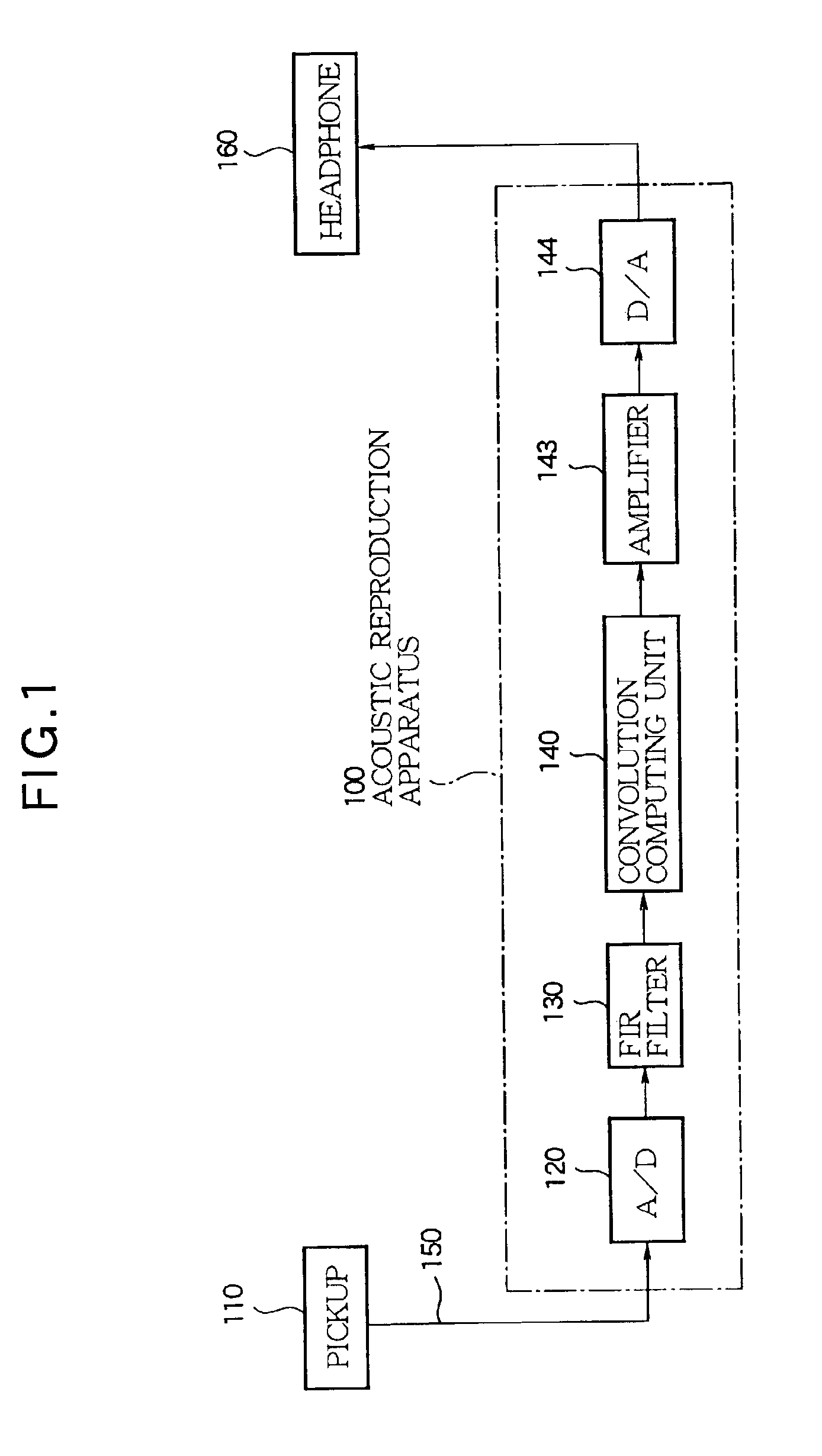
[0066]The acoustic reproduction apparatus 100 according to the embodiment comprises the FIR filter 130 assigned with one derived filter characteristic and the convolution computing unit 140 to convolute with the one derived filter characteristic. It may be preferable to appropriately change either or both of the filter characteristic of the FIR filter 130 and the impulse response convoluted by the convolution computing unit 140.

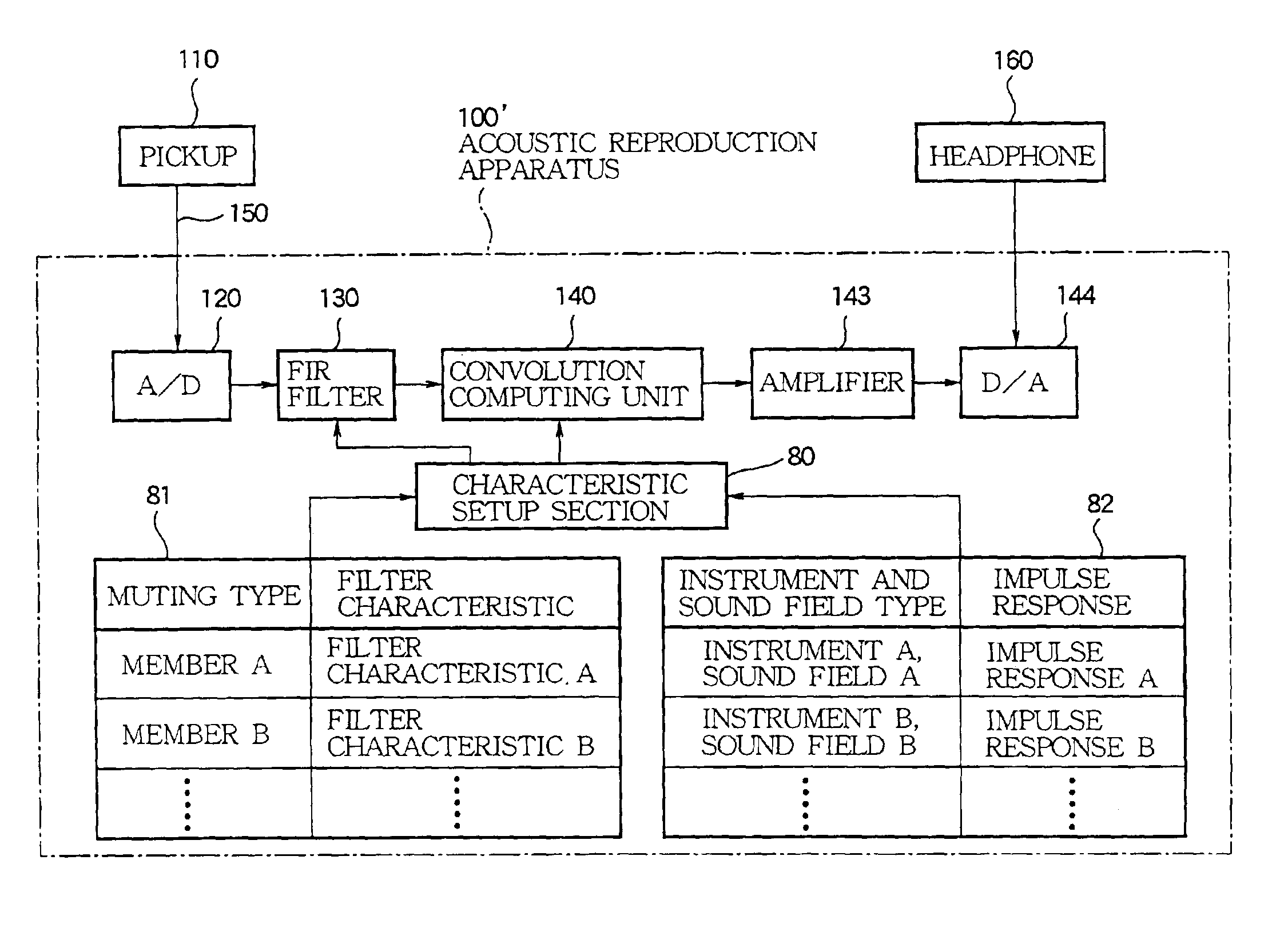
[0067]As shown in FIG. 8, for example, it may be preferable to implement the same mute performance as the above-mentioned embodiment by using an acoustic reproduction apparatus 100′ that further comprises a characteristic setup section (characteristic selection means or selection means 80, a filter characteristic storage section 81, and an impulse response storage section 82 in addition to the configuration of the acoustic reproduction apparatus 100.

[0068]The characteristic setup section 80 in FIG. 8 follows an instruction of a user (per...

modification 2

[0076](Modification 2)

[0077]The above-mentioned embodiment determines the filter characteristic of the FIR filter 130 in accordance with a difference between the signal detected by the pickup 110 with the mute member 301 attached to the violin 200 and the signal detected by the pickup 110 with the mute member 301 not attached to the violin 200. In this manner, it may be preferable to determine the filter characteristic in accordance with a difference between signals that are detected with the mute member 301 attached or not attached to the same violin 200. It may be also preferable to use another violin, e.g., with a higher grade than that of the violin 200 in order to obtain signals during the normal performance. Like the above-mentioned embodiment, the FIR filter 130 is assigned with the filter characteristic corresponding to a difference between the signal detected by the pickup attached to the bridge of the high grade violin and the signal detected by the pickup 110 of the violi...

modification 3

[0078](Modification 3)

[0079]FIG. 9 shows a configuration of an acoustic reproduction apparatus 100″ provided with a reproduction correction filter 90 after the convolution computing unit 140 in the acoustic reproduction apparatus 100. It may be preferable to reproduce a sound field that makes the performer to feel as if he or she listened to a musical sound without using the headphone while actually listening to the sound from the headphone 160. More specifically, the headphone 160 is mounted on a dummy head and generates an impulse sound. A microphone picks up the impulse sound generated from the headphone 160. A signal of the received impulse sound is inversely transformed to yield a characteristic that is assigned as the filter characteristic of the reproduction correction filter 90. Since such filter characteristic is assigned to the reproduction correction filter 90, it is possible to reproduce a sound field that makes the performer to feel as if he or she listened to a musical...


PUM


Abstract

A method is provided for designing an acoustic correction filter applicable to a stringed instrument, which is composed of a string member operable to undergo a vibration, a support member for supporting the string member, a body member responsive to the vibration transmitted through the support member for generating a natural sound and a mute attachment for muting the natural sound. The acoustic correction filter is operable when the natural sound is muted by the mute attachment for filtering a signal derived from the vibration so as to create an artificial sound instead of the muted natural sound. The method is carried out by the steps of acquiring a first sample signal from the vibration under a mute state, acquiring a second sample signal from the vibration under a free state, extracting a difference between the acquired first sample signal and the acquired second sample signal, and determining a correction characteristic of the acoustic correction filter based on the extracted difference such that the acoustic correction filter can filter the signal in accordance with the determined correction characteristic so as to create the artificial sound comparable to the natural sound.

Description

BACKGROUND OF THE INVENTION[0001]1. Technical Field of the Invention[0002]The present invention relates to an acoustic signal output apparatus that corrects a signal detected from a vibration of a stringed instrument and outputs an acoustic signal, a filter characteristics determination apparatus for an acoustic correction filter used in the acoustic signal output apparatus, and methods of designing and forming the acoustic correction filter.[0003]2. Prior Art[0004]Conventionally, there is used an electric stringed instrument simulating a natural stringed instrument such as a violin and the like. The electric stringed instrument uses a pickup to detect a string vibration and amplifies the detected signal for output of sound. Such an electric stringed instrument enables a so-called mute performance in which a detected signal is output to a headphone and the like. The electric stringed instrument is very useful as a musical training tool used for practice in a situation where it is no...

Claims


Application Information

Patent Timeline
IPC IPC(8): G10H1/06G10H3/00G10H1/12G10H3/18G10H1/02
CPCG10H1/125G10H3/185G10H3/186Y10S84/09G10H2250/115G10H2250/145
Inventor MIYAZAKI, HIDEOKISHINAGA, SHINJITAKABAYASHI, YOUJIRO
Owner YAMAHA CORP
Why Eureka
Try Eureka