Shingle system and method

Inactive Publication Date: 2005-04-26
SUNPOWER CORPORATION
View PDF76 Cites 139 Cited by
  • Summary
  • Abstract
  • Description
  • Claims
  • Application Information

AI Technical Summary

Benefits of technology

[0008]Various aspects of the present invention provide significant advantages to the user. A primary advantage relates to temperature regulation, the temperature regulation being achieved in part by the use of a venting region between the barrier and the base. The provision of a venting region helps reduce the temperature of the PV module, when the barrier comprises a PV module, which helps to increase the efficiency of the PV module over the efficiency of a PV module mounted to a support surface without a venting region. This reduction in temperature under typical summertime operating conditions in central California, such as Sacramento, has been found to be about 20°C., representing about a 10 percent increase in PV efficiency. This increase in efficiency helps to reduce

Problems solved by technology

Primary among the factors are cost and aesthetics.
However, photovoltaic shingle systems have not been as widely accepted as hoped-for because 1) PV mounted integrally with the building roof as shingles operate at higher temperatures, causing a reduction in PV electrical output due to an inverse relationship between temperature and PV efficiency; 2) the same higher operating temperatures approach or exceed the upper limit of the warranted PV operating temperature (typically 80 degrees C.) and serve to shorten the useful life of the PV shingle; 3) some products call for electrical c

Method used


Image

  • Shingle system and method
  • Shingle system and method
  • Shingle system and method

Examples


Example

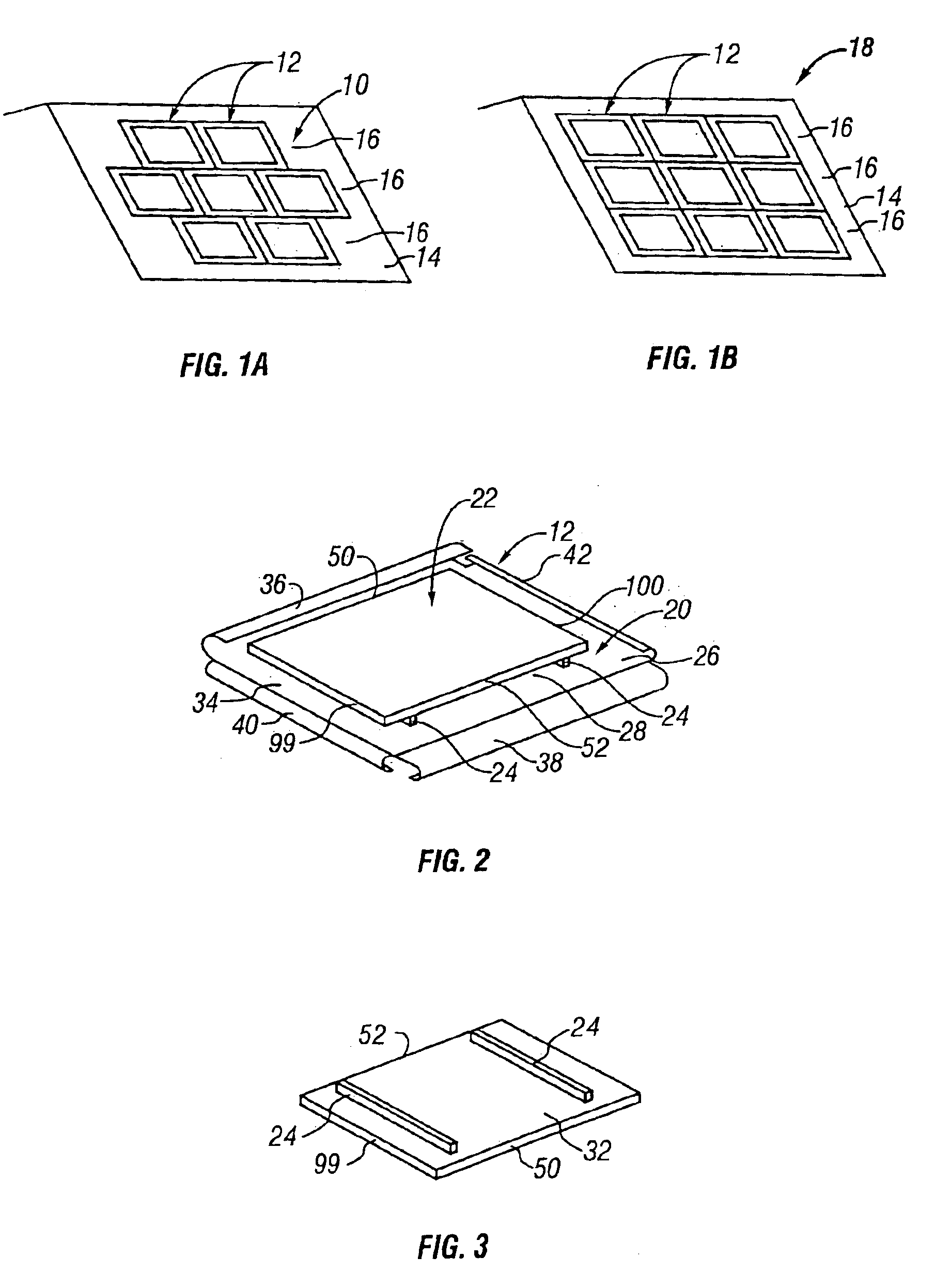
[0037]The present invention is directed to shingle assemblies that can be mounted to inclined surfaces, such as the roof of a building, with the shingle assemblies in one row being either laterally offset or laterally aligned with the shingle assemblies in adjacent rows. FIG. 1A illustrates an array 10 of PV shingle assemblies 12 mounted to an inclined roof 14 with the rows 16 of shingle assemblies 12 laterally offset from one another. FIG. 1B shows an array 18 of PV shingle assemblies 12 also mounted to an inclined roof 14 with the rows 16 of shingle assemblies 12 laterally aligned with the shingle assemblies in an adjacent row. While the present invention will typically refer to the inclined support surface as roof 14, other inclined support surfaces, such as shed, deck, walkway covering, lattice structure, may also be used. Various embodiments of shingle assemblies will be described below with like elements being referred to with like reference numerals.

[0038]FIGS. 2 and 3 illust...


PUM

PropertyMeasurementUnit
Temperatureaaaaaaaaaa
Forceaaaaaaaaaa
Adhesivityaaaaaaaaaa

Abstract

A barrier, such as a PV module, is secured to a base by a support to create a shingle assembly with a venting region defined between the barrier and base for temperature regulation. The bottom edges of the barriers of one row may overlap the top edges of the barriers of another row. The shingle assemblies may be mounted by first mounting the bases to an inclined surface; the barriers may be then secured to the bases using the supports to create rows of shingle assemblies defining venting regions between the barriers and the bases for temperature regulation.

Description

CROSS REFERENCE TO RELATED APPLICATIONS[0001]This is related to the applicant's following U.S. patent applications filed on the same date as this application: Shingle Assembly, Ser. No. 10 / 078,918; Shingle System, Ser. No. 10 / 078,916.FEDERALLY SPONSORED RESEARCH OR DEVELOPMENT[0002]This invention was made with government support under DOE SBIR contract DE-FG03 99 ER82862 awarded by the Department of Energy. The government has certain rights in this invention.BACKGROUND OF THE INVENTION[0003]Roofing shingles come in two primary types. A first type is typically flat and is designed so that there is a generous amount of overlap between adjacent shingles to create weather resistant joints to help ensure weather tightness. This first, edge-overlapping type may be flexible, such as the common composition or asphalt shingle, or it may be rigid, such as slate or some concrete shingles. A second type of roofing shingle has interlocking edges to secure the edges to one another and to help cre...

Claims


Application Information

Patent Timeline
IPC IPC(8): E04D1/20E04D1/12E04D1/18E04D3/40E04D1/30E04D13/18H01L31/048
CPCE04D1/18E04D1/20F24J2/5262H02S20/23Y02B10/12Y02E10/47F24J2002/0053F24S2020/12F24S25/67Y02E10/50Y02B10/10E04D1/2916E04D1/2918E04D1/30
Inventor DINWOODIE, THOMAS L.
Owner SUNPOWER CORPORATION
Why Eureka
Try Eureka