Light bulb changer

a technology of light bulb and handle, which is applied in the direction of manipulators, gripping heads, kitchen equipment, etc., can solve the problems of not being able to adjust the handle to different heights, and not having a flexible arm for reaching light bulbs

Inactive Publication Date: 2005-04-26
SUGANO NORIO
View PDF96 Cites 36 Cited by
  • Summary
  • Abstract
  • Description
  • Claims
  • Application Information

AI Technical Summary

Benefits of technology

[0007]A light bulb changer includes an outer tube and an inner tube positioned within the outer tube. The outer and inner tubes are adjustable along a longitudinal axis in relation to each other. The inner tube has a rotating member which is rotatable about the longitudinal axis by a corresponding grip. The light bulb changer also includes a flexible arm coupled with the outer tube with a flex cable running through the arm. The flex cable in the flexible arm rotates in agreement with the rotating member by means of a transferring mechanism and drives a clasping mechanism comprising a plurality of spring urged fingers. The spring urged fingers are adjustable to clasp different sized light bulbs by a sliding collar coupled to the clasping mechanism. The device also comprises a locking mechanism for allowing or preventing the outer tube and the inner tube from sliding relative to each other at any position when the locking mechanism is engaged.

Problems solved by technology

One such problem is accessibility.
Another problem stems from the variety of angles from which bulbs must be extracted and replaced from these remote locations, such as from chandeliers and hanging light arrangements.
Another problem is the adjustability of the handle to reach light bulbs at varying distances.
Further, the handle in this patent does not have a flexible arm for reaching light bulbs that are at an angle.
However, the device taught by Maki, by having a fixed rod, does not allow the user to adjust the rod to different heights.
This is disadvantageous to the user, because the cup is not adjustable to engage different sized light bulbs.
Although this light bulb changer allows the user to bend the arm to engage light bulbs at different angles, the light bulb changer does not allow the user to adjust the handle to different heights.
Further, the light bulb changer taught by Negley does not allow the user to adjust the mechanism to fit differently sized light bulbs.
However, the pivoting section is locked by tightening the clamp screw, which is burdensome on the user, because the user must use a screw driver, or some other external tool, to lock the pivoting shaft.
Further, the rods taught in this patent are also adjustable to reach light bulbs at different heights, but the mechanism to lock the rods at a desired height is limiting.
Therefore, the user can only adjust the rod at certain heights, which is burdensome if the light bulb is at a height that does not correspond to any of the positions available on the rod.

Method used


Image

  • Light bulb changer
  • Light bulb changer
  • Light bulb changer

Examples


Embodiment Construction

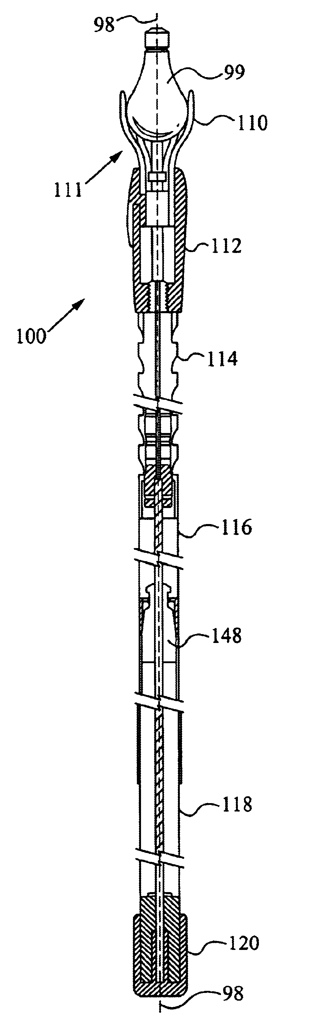
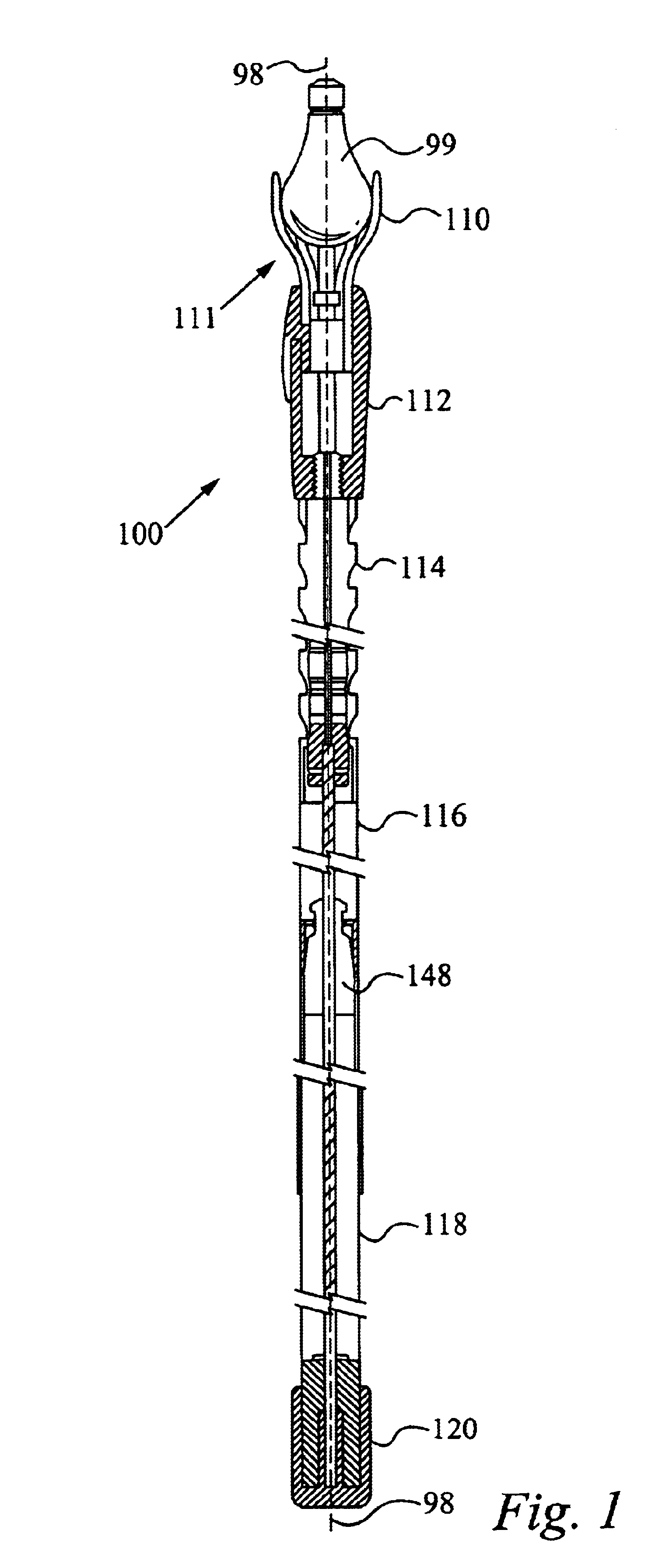
[0013]FIG. 1 shows a segmented cross sectional view of the light bulb changer device 100 for engaging a light bulb 99. Generally, the device 100 shown in FIG. 1 has a clasping mechanism 111 comprising several fingers 110 for clasping the light bulb 99, a head unit 112, a flexible arm 114, an outer tube 116, an inner tube 118 located within the outer tube 118 slidable along a longitudinal axis 98 which passes through the center of both tubes, and a turning grip 120 coupled to the inner tube 118. The specifics of each section will be discussed in detail below and in the additional drawings.

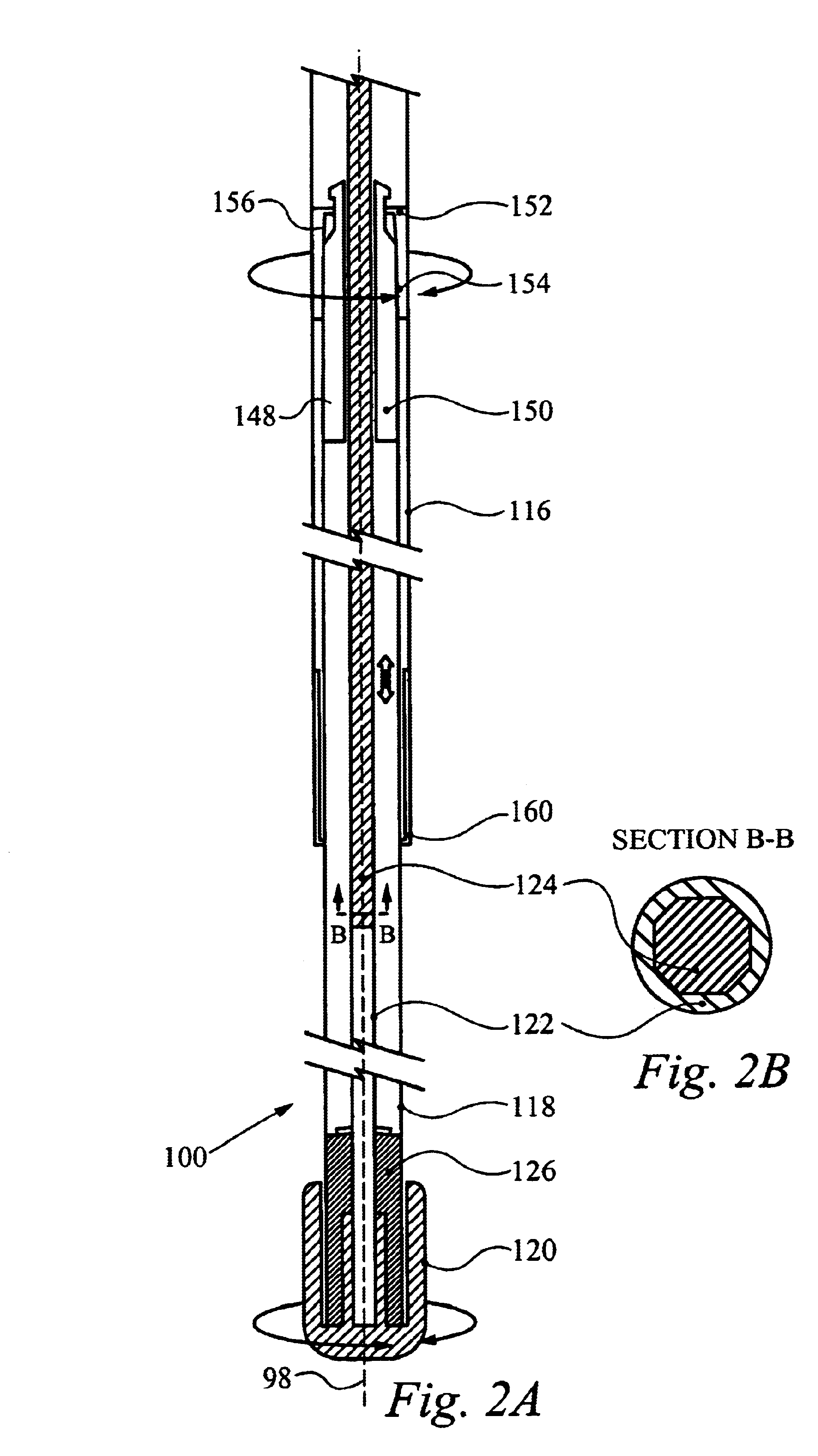
[0014]FIG. 2a illustrates a cross sectional view of the light bulb changer 100 below the locking mechanism 148. The inner tube 118 has an upper and lower end and is positioned within the outer tube 116 which also has an upper and lower end. The tubes are also positioned such that the upper ends of the tubes and the lower ends of the tubes correspond to each other respectively and are slidable with r...


PUM


Abstract

A device for changing a light bulb comprising an outer tube and an inner tube positioned inside the outer tube, wherein the tubes are adjustable along a longitudinal axis. The inner tube having a rotating member which is rotatable about the longitudinal axis by a grip attached to the inner tube. The device comprising a flexible arm with a flex cable running through the arm, wherein the arm is connected to the outer tube. The flex cable in the flexible arm rotates in agreement with the rotating member by means of a transferring mechanism and drives a clasping mechanism comprising a plurality of spring urged fingers. The spring urged fingers are adjustable to clasp different sized light bulbs by an sliding collar coupled to the clasping mechanism. The device also comprises a locking mechanism for allowing or preventing the outer tube and the inner tube from sliding relative to each other at any position.

Description

FIELD OF THE INVENTION[0001]The present invention relates to a remote access tool. More specifically, the present invention relates to a device designed to remove and replace light bulbs which are held at a variety of angles and heights and are otherwise inaccessible from ground level.BACKGROUND OF THE INVENTION[0002]Numerous light bulb removal tools have been patented which alleviate the problems associated with replacing light bulbs from remote locations. One such problem is accessibility. Overhead lights are purposefully positioned out of reach to minimize risks associated with heat burns and unintentional contact which could result in globe glass breakage. Another problem stems from the variety of angles from which bulbs must be extracted and replaced from these remote locations, such as from chandeliers and hanging light arrangements. Another problem is the adjustability of the handle to reach light bulbs at varying distances.[0003]U.S. Pat. No. 1,514,814 to Allen, discloses an...

Claims


Application Information

Patent Timeline
Patent Type & Authority Patents(United States)
IPC IPC(8): H01K3/32H01K3/00
CPCH01J9/003H01K3/32
Inventor SUGANO, NORIO
Owner SUGANO NORIO
Why Eureka
Try Eureka