Apparatus for reducing fluid drawback through a medical valve

a technology of medical valves and apparatus, which is applied in the field of medical products, can solve the problems of blood leakage proximally into various parts of the valve, compromising affecting the sterility of the valve, so as to reduce the potential for fluid drawback

Inactive Publication Date: 2005-04-26
NP MEDICAL
View PDF150 Cites 208 Cited by
  • Summary
  • Abstract
  • Description
  • Claims
  • Application Information

AI Technical Summary

Benefits of technology

[0008]In accord with another aspect of the invention, a medical valve having an open mode for permitting fluid flow through the valve, and a closed mode for preventing fluid flow through the valve, includes an interior wall defining a variable volume fluid chamber, and a compressible member within the variable volume fluid chamber. The compressible member and interior wall together define both a closed chamber volume within the fluid chamber when the valve is in the closed mode, and an open chamber volume when the valve is in the open mode. The closed chamber volume preferably is no greater than the open chamber volume, thus reducing the potential for fluid drawback that may result when transitioning from the open mode to the closed mode.

Problems solved by technology

Problems arise, however, when the syringe is withdrawn from the valve.
More particularly, a back pressure produced by withdrawing the syringe undesirably can cause blood to leak proximally into various parts of the valve.
In addition to coagulating and impeding the mechanical operation of the valve, blood in the valve also compromises the sterility of the valve.

Method used


Image

  • Apparatus for reducing fluid drawback through a medical valve
  • Apparatus for reducing fluid drawback through a medical valve
  • Apparatus for reducing fluid drawback through a medical valve

Examples


first embodiment

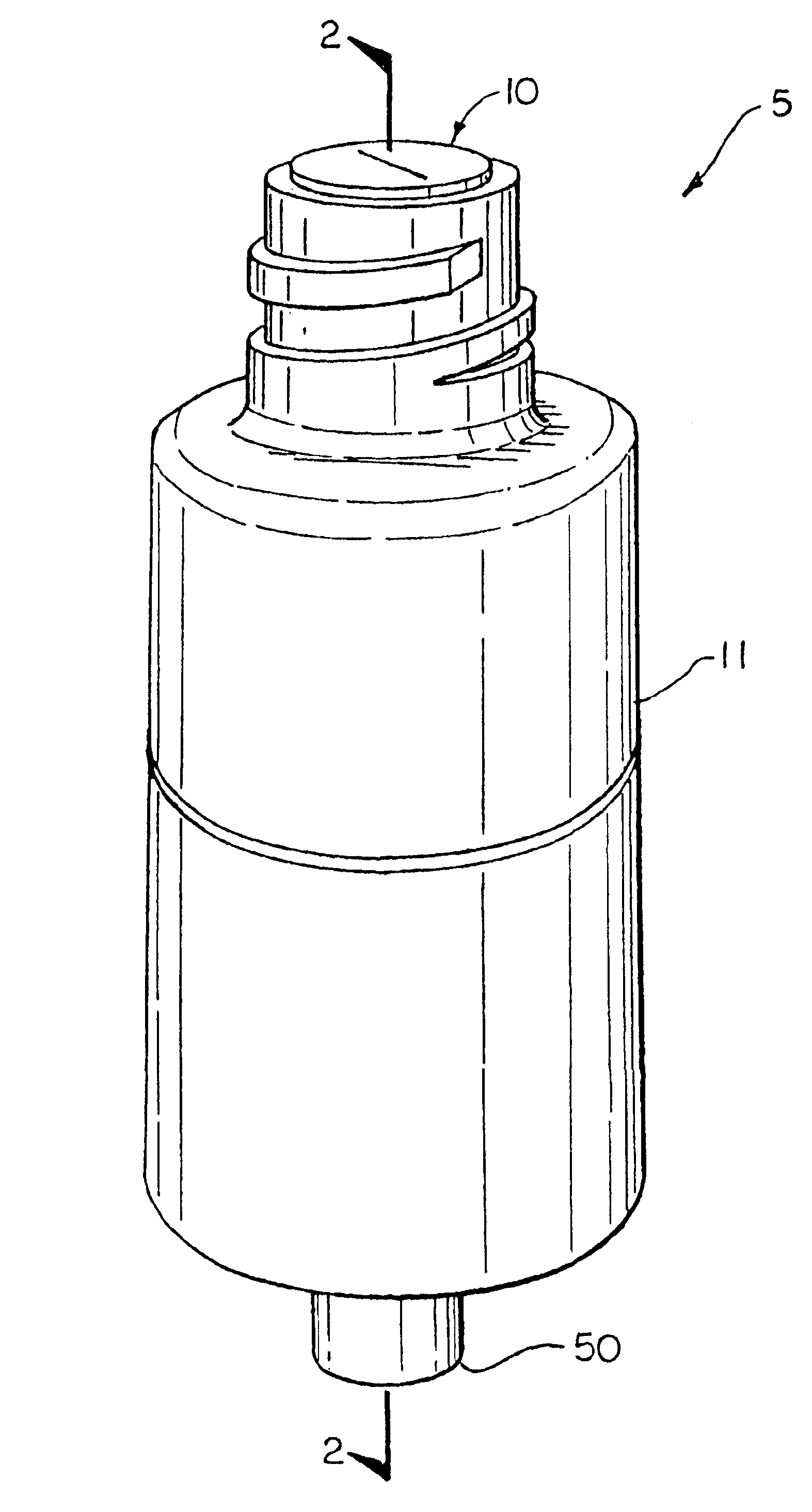
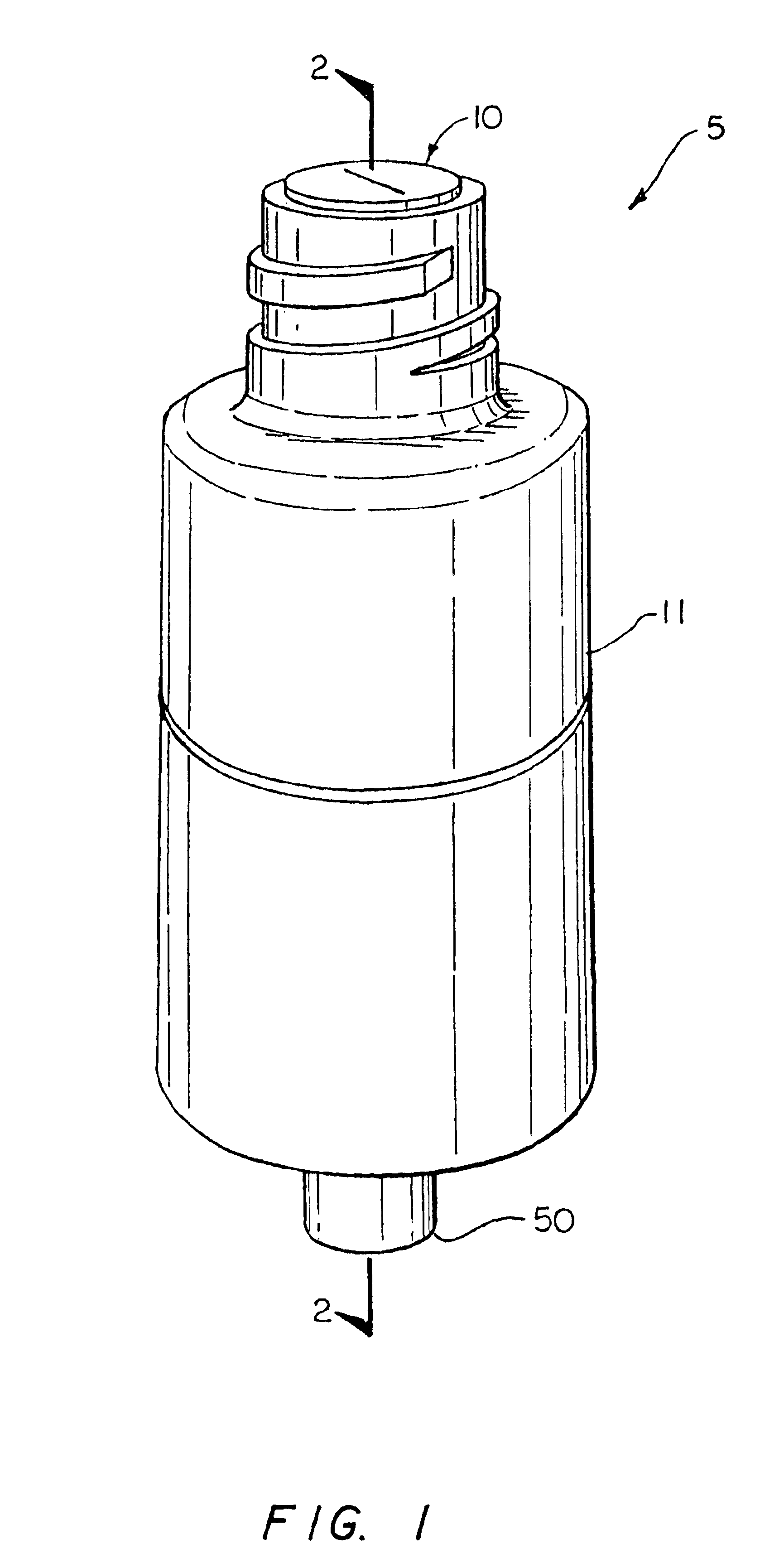
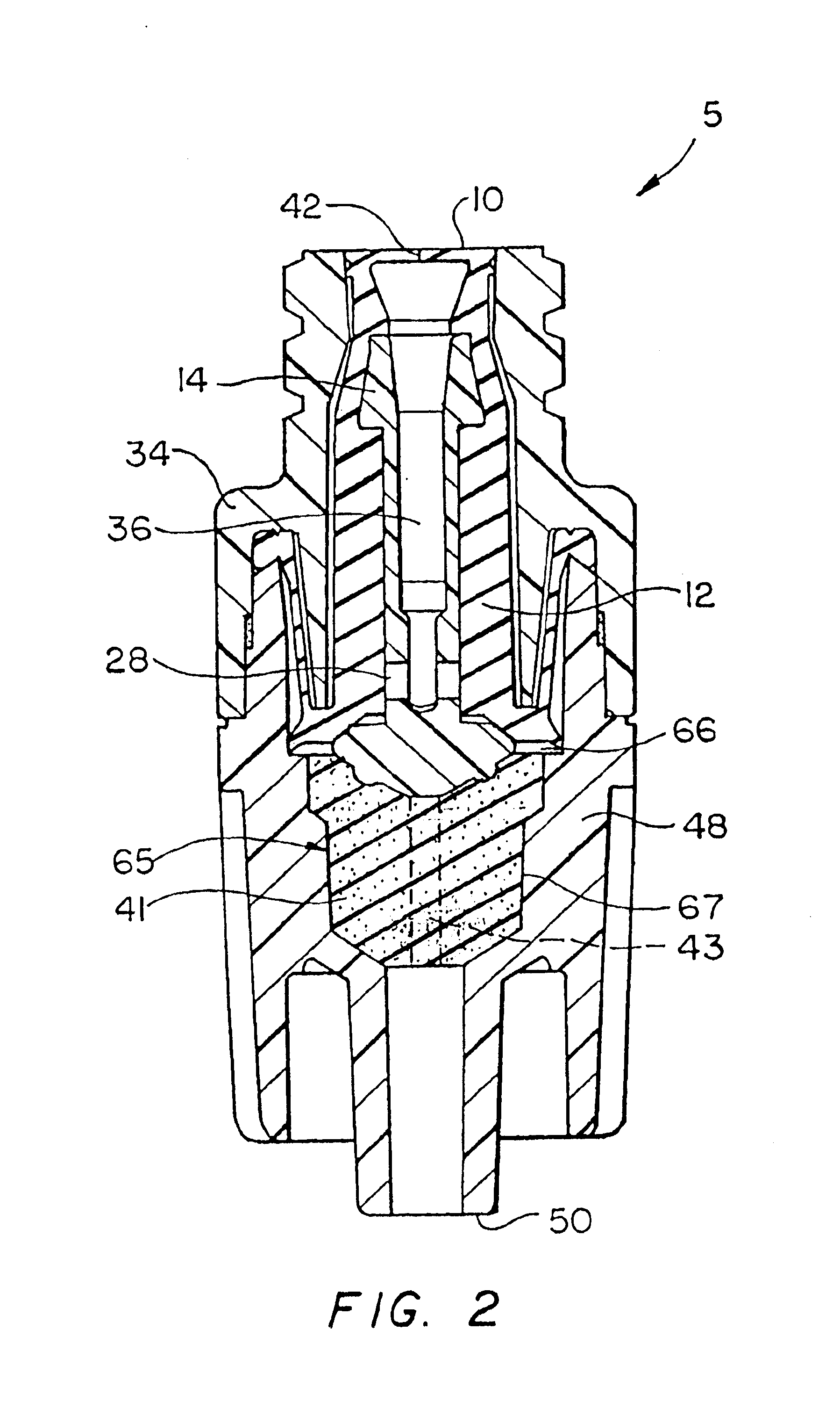
[0026]FIG. 2 schematically shows a cross-sectional view of the medical valve 5 shown in FIG. 1 along line 2—2. Among other things, the valve 5 includes an inlet housing portion 34 having the proximal port 10, an outlet housing portion 48 having the distal port 50, a stretchable and compressible gland 12 secured between the inlet housing 34 and outlet housing 48, and a rigid, longitudinally movable cannula 14 secured within the valve 5 by the gland 12. The cannula 14 forms a cannula flow channel 36 terminating at a transverse channel 28 that normally is occluded by the gland 12. In addition, the outlet housing 48 forms a chamber 65 having a volume that changes as the cannula 14 is urged proximally and distally by a nozzle.

[0027]Insertion of a nozzle against a slit 42 at the proximal end of the gland 12 causes the cannula 14 to move distally, thereby moving the transverse channel 28 from its occluding contact with the gland 12. Liquid then may be directed first through the cannula cha...

second embodiment

[0035]FIG. 4 shows a cross-sectional view of the valve 5 shown in FIG. 1. In this embodiment, the outlet housing portion 48 is reconfigured to have an orthogonal outlet 100 for directing fluid from the valve 5, and an end cap 102 at its distal end. Further unlike the embodiment shown in FIG. 1, the compressible member 41 is in the form of a hollow cylinder having a closed top portion, and an open bottom portion (FIG. 5A). In particular, the top portion comprises a top surface 104 having a depression 106 for receiving the bottom portion of the cannula 14. The bottom portion includes an annular flange 108 for securing the compressible member 41 within the valve 5 (discussed below). The compressible member 41 may be manufactured from any material used in the art, such as silicone, latex, or plastic, that can compress and decompress without significantly affecting its overall structure.

[0036]As shown in FIG. 4, the compressible member 41 is free standing within the chamber 65. According...


PUM


Abstract

A medical valve for valving fluid includes a housing defining a chamber having an inlet, an outlet, and an interior wall, a compressible member within the chamber, and a fluid channel defined by the interior wall. The fluid channel directs fluid received from the inlet toward the outlet.

Description

[0001]This application is a continuation-in-part U.S. patent application Ser. No. 09 / 394,169, filed Sep. 13, 1999 now U.S. Pat. No. 6,039,302 which is a continuation of U.S. patent application Ser. No. 08 / 970,125, filed Nov. 13, 1997 now abandoned, which claims priority from U.S. provisional patent application No. 60 / 034,708, filed Jan. 3, 1997, and U.S. provisional patent application No. 60 / 031,175, filed Nov. 18, 1996, and also claims priority from U.S. provisional patent application Ser. No. 60 / 117,359, filed Jan. 27, 1999, and entitled, “Apparatus for Reducing Fluid Drawback Through a Medical Valve.”FIELD OF THE INVENTION[0002]The invention generally relates to medical products and, more particularly, the invention relates to devices for reducing backflow through a medical valve.BACKGROUND OF THE INVENTION[0003]Medical valving devices commonly are utilized to valve fluids injected into and withdrawn from a patient. One exemplary type of medical valving device, known in the art a...

Claims


Application Information

Patent Timeline
Patent Type & Authority Patents(United States)
IPC IPC(8): A61M39/26A61M39/00A61M39/04A61M39/16F16K1/12F16K15/14
CPCA61M39/26F16K1/12A61M39/045A61M39/16A61M2039/261A61M2039/267A61M2039/266Y10S604/905A61M2039/263A61M2039/0036F16K15/144
Inventor NEWTON, BRIAN L.GANEM, CHARLES F.
Owner NP MEDICAL
Why Eureka
Try Eureka