Lock release mechanism for foldable walkers

a folding walker and lock release technology, applied in mechanical devices, couplings, manufacturing tools, etc., can solve the problems of limited manual dexterity of handicapped people, limited dexterity, and prior art locking mechanisms used in connection with foldable walkers

Inactive Publication Date: 2005-05-03
MEDICAL DEPOT
View PDF22 Cites 73 Cited by
  • Summary
  • Abstract
  • Description
  • Claims
  • Application Information

AI Technical Summary

Problems solved by technology

Prior art locking mechanisms used in connection with foldable walkers have suffered from various drawbacks.
The drawbacks stem from the limited manual dexterity of handicapped people.
However, certain people with limited dexterity may be incapable of exerting enough downward force to activate such a lever and thus will be unable to operate the locking assembly.
Also, the lever handles of the prior art are often narrow.
This presents additional problems for users having diminished manual dexterity.
The narrowness of the handle makes finding and gripping the lever difficult.
However, during the period in which the handicapped user has released the handle, the handicapped user is unbalanced, creating a greater likelihood that the user may fall.
Moreover, by positioning the pin actuating plunger on a cross brace, the handicapped user with limited dexterity is required to use two hands in order to fold each side brace, e.g., using one hand to depress the plunger while the other hand folds in the side brace.

Method used


Image

  • Lock release mechanism for foldable walkers
  • Lock release mechanism for foldable walkers
  • Lock release mechanism for foldable walkers

Examples


Embodiment Construction

[0014]The present invention will now be described more fully hereinafter with reference to the accompanying drawings in which an exemplary embodiment of the invention is shown. This invention may, however, be embodied in many different forms and should not be construed as being limited to the embodiment set forth herein. Rather, the embodiment is provided so that this disclosure will be thorough and complete, and will fully convey the scope of the invention to those skilled in the art.

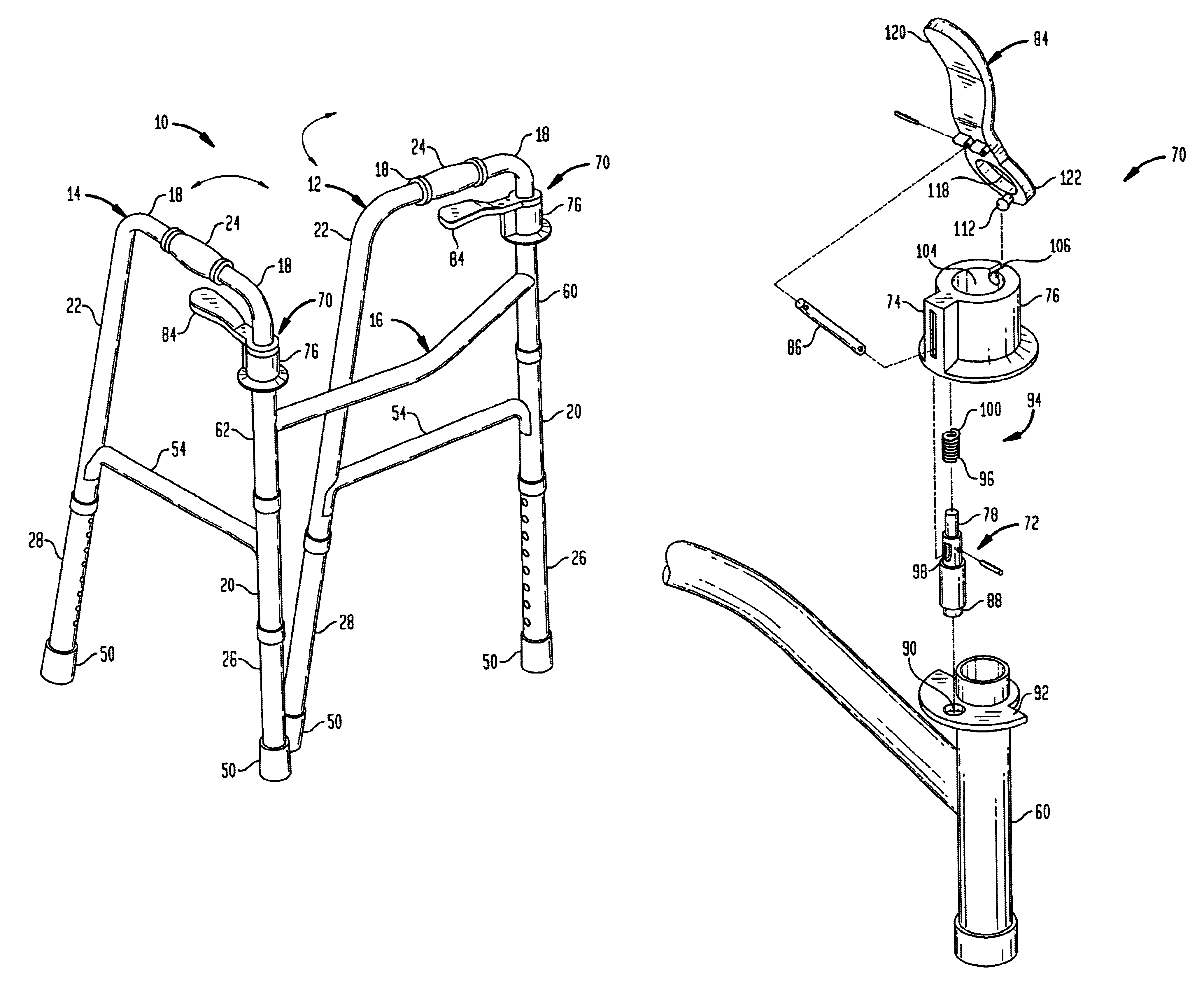
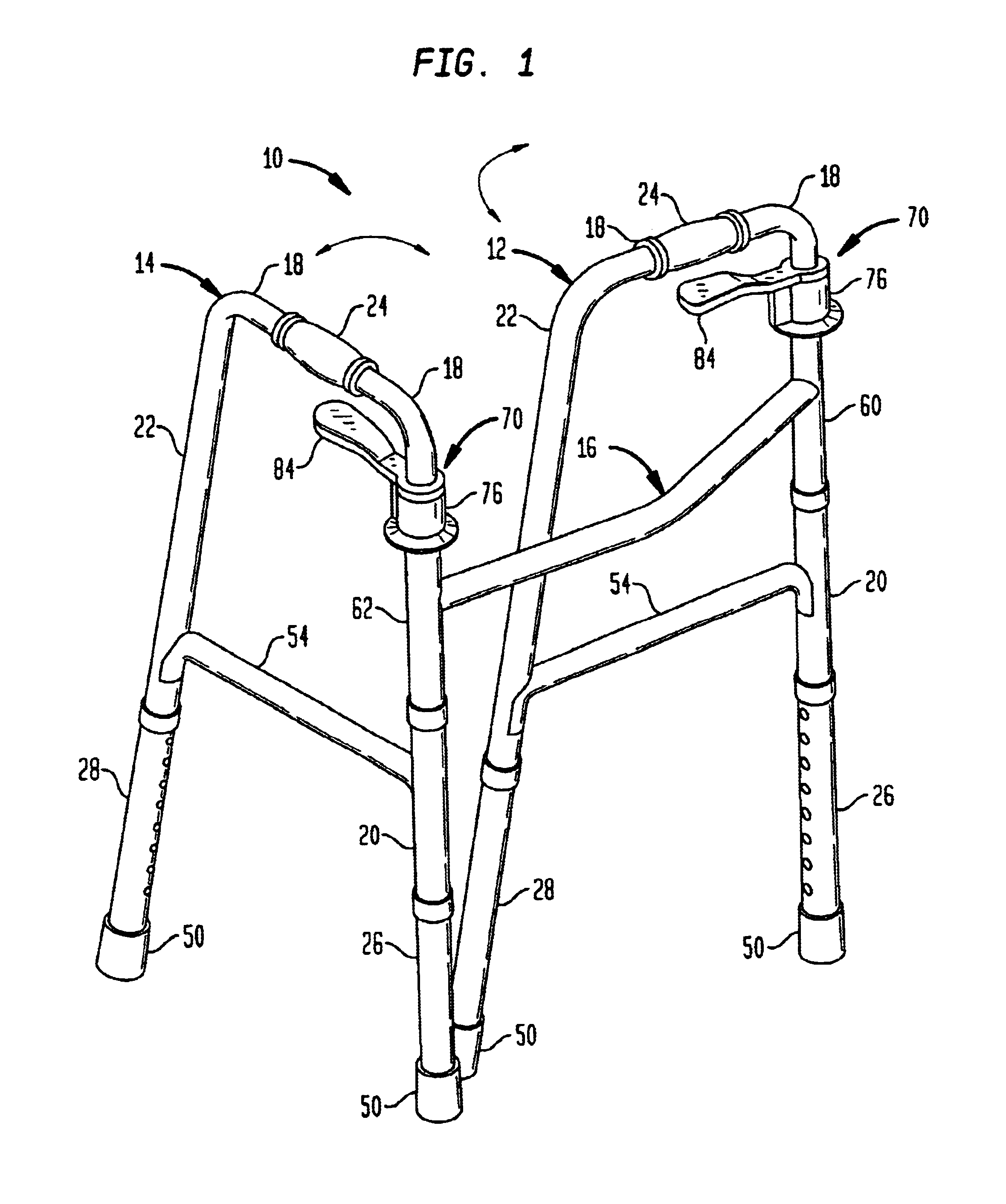
[0015]Referring now to the drawings wherein the showings are for purposes of illustrating an exemplary embodiment of the invention only and not for purposes of limiting same, FIG. 1 shows a walker 10 which includes a pair of spaced side frames 12 and 14 and a cross brace 16 for connecting the two side frames. Side frames 12 and 14, and cross brace 16 can be made from a lightweight and sturdy metallic material such as conventional aluminum or steel. Preferably, the metallic material of the side frames a...


PUM


Abstract

A locking assembly is disclosed for use with a walker having foldable side members. The locking assembly includes a locking pin movable between a first position in which the corresponding side member is held in a locked, unfolded state and a second position in which the side member is in an unlocked, folded state. A lock plate extends transversely to the longitudinal axis of the corresponding side member, and includes an aperture adapted to receive a locking end of the locking pin when the pin is in its first position. A lever is coupled to the locking pin such that when the lever is pivoted by upwardly applied pressure, the locking pin is moved from its first position to its second position to permit rotation of the corresponding side member to its folded state.

Description

BACKGROUND OF THE INVENTION[0001]1. Technical Field of the Invention[0002]This invention relates generally to a locking assembly, and more particularly to a locking assembly for use with a foldable walker.[0003]2. Description of the Related Art[0004]Prior art locking mechanisms used in connection with foldable walkers have suffered from various drawbacks. The drawbacks stem from the limited manual dexterity of handicapped people. For example, some prior art assemblies are operated through use of a lever. At least one of these devices requires the user of the walker to push down on the lever to allow for the walker to be folded. However, certain people with limited dexterity may be incapable of exerting enough downward force to activate such a lever and thus will be unable to operate the locking assembly. Also, the lever handles of the prior art are often narrow. This presents additional problems for users having diminished manual dexterity. The narrowness of the handle makes finding...

Claims


Application Information

Patent Timeline
Patent Type & Authority Patents(United States)
IPC IPC(8): A45B7/00A61H3/00
CPCA45B7/00A61H3/00A45B2009/007Y10T403/595A61H2201/0161Y10T403/59
Inventor DIAMOND, HARVEY
Owner MEDICAL DEPOT
Why Eureka
Try Eureka