Electrostatic fluid accelerator

a fluid accelerator and electrostatic technology, applied in the direction of instruments, particle separator tube details, corona discharge, etc., can solve the problems of not producing significant speed of air movement, substantial quantities of ozone and nitrogen oxides, and affecting the environment, and achieve the effect of reducing the rate of fluid flow

Inactive Publication Date: 2005-05-03
TESSERA INC
View PDF161 Cites 43 Cited by
  • Summary
  • Abstract
  • Description
  • Claims
  • Application Information

AI Technical Summary

Benefits of technology

[0016]The present Electrostatic Fluid Accelerator employs two fundamental techniques to achieve significant speeds in the fluid flow, which can be virtually any fluid but is most often air, and which will not produce substantial undesired ozone and nitrogen oxides when the fluid is air.

Problems solved by technology

To date, even these high initial ionic velocities have not produced significant speeds of air movement.
And, even worse, such high ionic velocities cause such excitation of surrounding air molecules that substantial quantities of ozone and nitrogen oxides, all of which have well-known detrimental environmental effects, are produced.
These result in a slight loss of efficiency because they tend to be drawn back to the anode.
Furthermore, the distance required for such recombination as does occur is very probably so great that it would be a detriment to using multiple stages to provide increased speed to the air.

Method used


Image

  • Electrostatic fluid accelerator
  • Electrostatic fluid accelerator
  • Electrostatic fluid accelerator

Examples


first embodiment

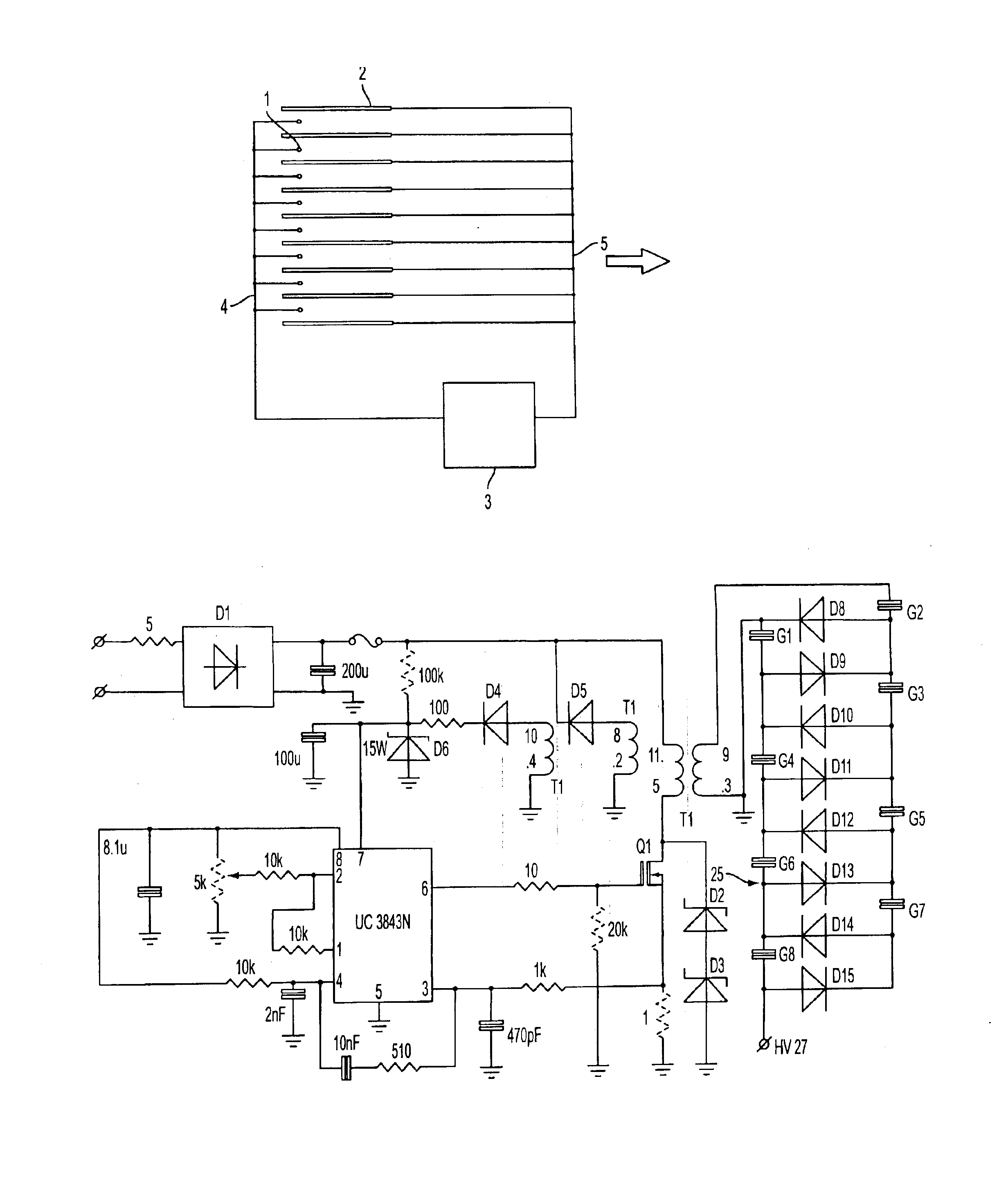
[0051]FIG. 1 illustrates schematically electrostatic fluid accelerator according to the invention which comprises multiple corona electrodes 1, multiple exciting electrodes 2, power supply 3. Corona electrodes 1 and exciting electrodes 2 are connected to the respective terminals of the power supply 3 by the means of conductors 4 and 5. The desired fluid flow is shown by an arrow. Corona electrodes 1 are located asymmetrically between exciting electrodes 2 with respect to the desired fluid flow. In the illustrated embodiment is assumed that corona electrodes 1 are wire-like electrodes (shown in cross section), exciting electrodes 2 are plate-like electrodes (also shown in cross section) and a power supply 3 is a DC power supply. It will be understood that corona electrodes may be of any shape that ensures corona discharge and subsequent ion emission from one or more parts of said corona electrode. In general corona electrodes may be made in shape of needle, barbed wire, serrated plat...

second embodiment

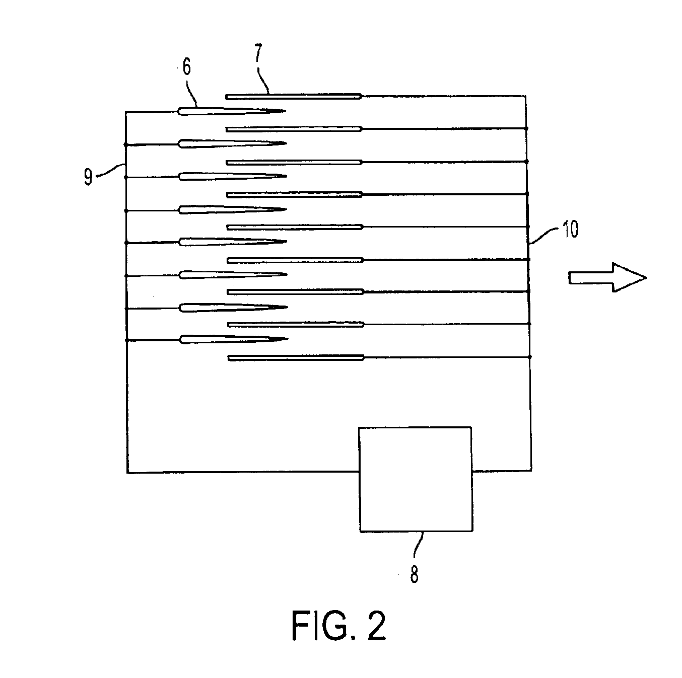
[0052]FIG. 2 illustrates schematically electrostatic fluid accelerator according to the invention which comprises multiple corona electrodes 6, multiple exciting electrodes 7, power supply 8. Corona electrodes 6 and exciting electrodes 7 are connected to the respective terminals of the power supply 8 by the means of conductors 9 and 10. The desired fluid flow is shown by an arrow. Corona electrodes 6 are located asymmetrically between exciting electrodes 7 with respect to the desired fluid flow. Corona electrodes 6 and exciting electrodes 7 are connected to the respective terminals of the power supply 8 by the means of conductors 9 and 10. The desired fluid flow is shown by an arrow. Corona electrodes 6 are located asymmetrically between exciting electrodes 7 with respect to the desired fluid flow. In the illustrated embodiment is assumed that corona electrodes 6 are razor-like electrodes (shown in cross section), exciting electrodes 7 are plate-like electrodes (also shown in cross ...

third embodiment

[0053]FIG. 3 illustrates schematically electrostatic fluid accelerator according to the invention which comprises multiple corona electrodes 11, multiple exciting electrodes 12, multiple attracting electrodes 13, power supply 14. Corona electrodes 11 from one hand and exciting electrodes 12 and attracting electrodes 13 from other hand are connected to the respective terminals of the power supply 14 by the means of conductors 15 and 16. The desired fluid flow is shown by an arrow. Corona electrodes 11 are located between exciting electrodes 12 and separated by the last from each other. As an example wire-like corona electrodes 11 are shown in cross section, exciting electrodes 12 are plate-like electrodes and attracting electrodes 13 are wire-like or rod-like electrodes (also shown in cross section) and a power supply 14 is a DC power supply. It will be understood FIG. 3 may as well represent the corona electrodes 11 in any other shape that ensures electric field strength in the vici...


PUM


Abstract

An electrostatic fluid accelerator having a multiplicity of closely spaced corona electrodes. The close spacing of such corona electrodes is obtainable because such corona electrodes are isolated from one another with exciting electrodes. Either the exciting electrode must be placed asymmetrically between adjacent corona electrodes or an accelerating electrode must be employed. The accelerating electrode can be either an attracting or a repelling electrode. Preferably, the voltage between the corona electrodes and the exciting electrodes is maintained between the corona onset voltage and the breakdown voltage with a flexible top high-voltage power supply. Optionally, however, the voltage between the corona electrodes and the exciting electrodes can be varied, even outside the range between the corona onset voltage and the breakdown voltage, in to vary the flow of fluid. And, to achieve the greatest flow of fluid, multiple stages of the individual Electrostatic Fluid Accelerator are utilized with a collecting electrode between successive stages in order to preclude substantially all ions and other electrically charged particles from passing to the next stage, where they would tend to be repelled and thereby impair the movement of the fluid. Finally, constructing the exciting electrode in the form of a plate that extends downstream with respect to the desired direction of fluid flow also assures that more ions and, consequently, more fluid particles flow downstream.

Description

CROSS-REFERENCE TO RELATED APPLICATION[0001]This is a continuation of U.S. patent application Ser. No. 09 / 419,720 filed on Oct. 14, 1999, now U.S. Pat. No. 6,504,308, which claims the benefit of U.S. provisional application Ser. No. 60 / 104,573, filed Oct. 16, 1998, now abandoned.BACKGROUND OF THE INVENTION[0002]1. Field of the Invention[0003]This invention relates to a device for accelerating, and thereby imparting velocity and momentum to a fluid, especially to air, through the use of ions and electrical fields.[0004]2. Description of the Related Art[0005]A number of patents (see, e.g., U.S. Pat. Nos. 4,210,847 and 4,231,766) have recognized the fact that ions may be generated by an electrode (termed the “corona electrode”), attracted (and, therefore, accelerated) toward another electrode (termed the “attracting electrode”), and impart momentum, directed toward the attracting electrode, to surrounding air molecules through collisions with such molecules.[0006]The corona electrode m...

Claims


Application Information

Patent Timeline
Patent Type & Authority Patents(United States)
IPC IPC(8): H01J49/02H01J49/04B03C3/40H05H1/24F15D1/00H01J7/24H01T19/00H01T23/00
CPCH01J49/04H01T23/00H01T19/00
Inventor KRICHTAFOVITCH, IGOR A.FUHRIMAN, JR., ROBERT L.
Owner TESSERA INC
Why Eureka
Try Eureka