Electrostatic fluid accelerator
a fluid accelerator and electrostatic technology, applied in the direction of instruments, particle separator tube details, corona discharge, etc., can solve the problems ozone and nitrogen oxides are produced, and the speed of air movement is not significant, so as to achieve the effect of reducing the rate of fluid flow
- Summary
- Abstract
- Description
- Claims
- Application Information
AI Technical Summary
Benefits of technology
Problems solved by technology
Method used
Image
Examples
first embodiment
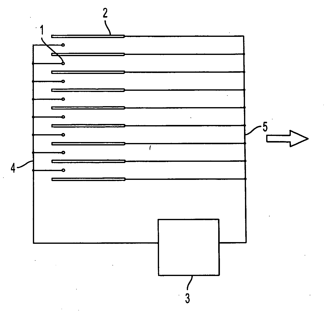
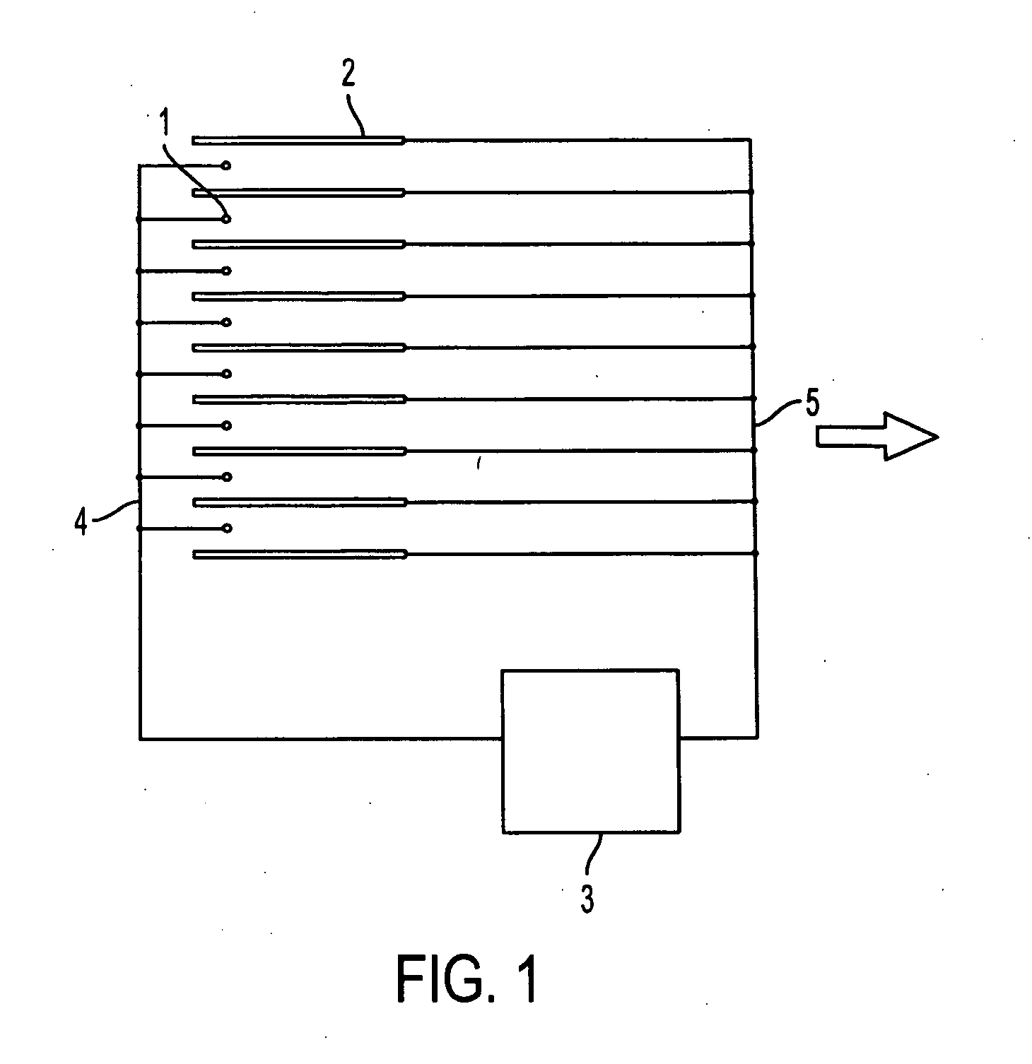
[0050]FIG. 1 illustrates schematically electrostatic fluid accelerator according to the invention which comprises multiple corona electrodes 1, multiple exciting electrodes 2, power supply 3. Corona electrodes 1 and exciting electrodes 2 are connected to the respective terminals of the power supply 3 by the means of conductors 4 and 5. The desired fluid flow is shown by an arrow. Corona electrodes 1 are located asymmetrically between exciting electrodes 2 with respect to the desired fluid flow. In the illustrated embodiment is assumed that corona electrodes 1 are wire-like electrodes (shown in cross section), exciting electrodes 2 are plate-like electrodes (also shown in cross section) and a power supply 3 is a DC power supply. It will be understood that corona electrodes may be of any shape that ensures corona discharge and subsequent ion emission from one or more parts of said corona electrode. In general corona electrodes may be made in shape of needle, barbed wire, serrated plat...
second embodiment
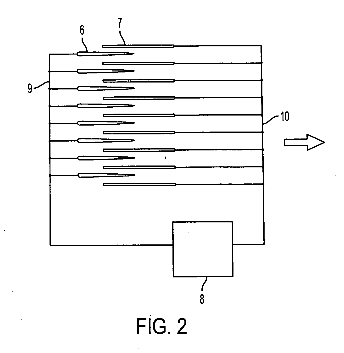
[0051]FIG. 2 illustrates schematically electrostatic fluid accelerator according to the invention which comprises multiple corona electrodes 6, multiple exciting electrodes 7, power supply 8. Corona electrodes 6 and exciting electrodes 7 are connected to the respective terminals of the power supply 8 by the means of conductors 9 and 10. The desired fluid flow is shown by an arrow. Corona electrodes 6 are located asymmetrically between exciting electrodes 7 with respect to the desired fluid flow. Corona electrodes 6 and exciting electrodes 7 are connected to the respective terminals of the power supply 8 by the means of conductors 9 and 10. The desired fluid flow is shown by an arrow. Corona electrodes 6 are located asymmetrically between exciting electrodes 7 with respect to the desired fluid flow. In the illustrated embodiment is assumed that corona electrodes 6 are razor-like electrodes (shown in cross section), exciting electrodes 7 are plate-like electrodes (also shown in cross ...
third embodiment
[0052]FIG. 3 illustrates schematically electrostatic fluid accelerator according to the invention which comprises multiple corona electrodes 11, multiple exciting electrodes 12, multiple attracting electrodes 13, power supply 14. Corona electrodes 11 from one hand and exciting electrodes 12 and attracting electrodes 13 from other hand are connected to the respective terminals of the power supply 14 by the means of conductors 15 and 16. The desired fluid flow is shown by an arrow. Corona electrodes 11 are located between exciting electrodes 12 and separated by the last from each other. As an example wire-like corona electrodes 11 are shown in cross section, exciting electrodes 12 are plate-like electrodes and attracting electrodes 13 are wire-like or rod-like electrodes (also shown in cross section) and a power supply 14 is a DC power supply. It will be understood FIG. 3 may as well represent the corona electrodes 11 in any other shape that ensures electric field strength in the vici...
PUM
 Abstract
Description
Claims
Application Information
 - R&D
- Intellectual Property
- Life Sciences
- Materials
- Tech Scout
- Unparalleled Data Quality
- Higher Quality Content
- 60% Fewer Hallucinations
Browse by: Latest US Patents, China's latest patents, Technical Efficacy Thesaurus, Application Domain, Technology Topic, Popular Technical Reports.
© 2025 PatSnap. All rights reserved.Legal|Privacy policy|Modern Slavery Act Transparency Statement|Sitemap|About US| Contact US: help@patsnap.com


