Recording apparatus and recording method

a recording apparatus and recording method technology, applied in the field of recording apparatus and recording method, can solve the problems of large amount of time required for recording images, small number of disks may be processed, and it may take a long time for ink to naturally dry, so as to reduce the speed of airflow and speed of airflow. the effect of the viscosity of the air flowing into between the shielding member and the image recording surfa

Inactive Publication Date: 2006-10-05
BROTHER KOGYO KK
View PDF2 Cites 12 Cited by
  • Summary
  • Abstract
  • Description
  • Claims
  • Application Information

AI Technical Summary

Benefits of technology

[0016] Further, in the recording apparatus according to the present invention, the shielding member may be inclined to a direction perpendicular to the direction of rotation of the recording medium, as viewed from a direction perpendicular to the image recording surface. In this case, most of the airflow generated by the viscosity of the air with the rotation of the recording medium can be directed to the inside or outside of the recording medium by the shielding member. Therefore, the speed of the airflow generated by the viscosity of the air flowing into between the shielding member and the image recording surface can be decreased. As a result, compared to the case in which the shielding member is not provided, the relative speed of the air to the recording medium increases in the region on the image recording surface which faces the shielding member, and in a region which is close to the region facing the shielding member and disposed in the downstream side in the direction of rotation of the recording medium, thus drying of the ink can be further accelerated.
[0017] In addition, in the recording apparatus according to the present invention, the shielding member may have an inclined surface and distance between the inclined surface and the image recording surface becomes larger toward the downstream in a direction of rotation of the recording medium. In this case, most of the airflow generated by the viscosity of the air with the rotation of the recording medium can be directed in a direction away from the image recording surface of the recording medium along the inclined surface, and the speed of the airflow generated by the viscosity of the air flowing into between the shielding member and the image recording surface can be decreased. As a result, compared to the case in which the shielding member is not provided, the relative speed of the air to the recording medium increases in the region on the image recording surface which faces the shielding member, and in a region which is close to the region facing the shielding member and disposed in the downstream side in the direction of rotation of the recording medium, thus drying of the ink can be further accelerated.
[0018] Further, in the recording apparatus according to the present invention, the shielding member may have a plurality of shielding column portions extending in a direction perpendicular to the image recording surface toward the image recording surface. In this case, the shielding column portions provided on the shielding member block the movement of the airflow flowing into between the shielding member and the image recording surface, whereby the speed of the airflow flowing into between the shielding member and the image recording surface can be reduced. As a result, compared to the case in which the shielding member is not provided, the relative speed of the air to the recording medium increases in the region on the image recording surface which faces the shielding member, and in a region which is close to the region facing the shielding member and disposed in the downstream side in the direction of rotation of the recording medium, thus drying of the ink can be further accelerated.
[0019] Further, in the recording apparatus according to the present invention, an inside of the shielding member is formed with an airflow path which returns an airflow, flowing along the recording medium from an upstream side in a direction of rotation of the recording medium, to the upstream side in the direction of rotation. In this case, the direction of movement of the airflow, which is generated by the viscosity of the air with the rotation of the recording medium and flows into the airflow path inside the shielding member, can be inverted by the airflow path and the airflow can be returned to the upstream side of the direction of rotation, whereby the speed of the airflow flowing into the between the shielding member and the image recording surface can be reduced. As a result, compared to the case in which the shielding member is not provided, the relative speed of the air to the recording medium increases in the region on the image recording surface which faces the shielding member, and in the region which is close to the region facing the shielding member and disposed in the downstream side in the direction of rotation of the recording medium, thus drying of the ink can be further accelerated.
[0020] Further, in the recording apparatus according to the present invention, the shielding member may be disposed so as to face an entire region of the image recording surface of the recording medium, excluding a region on the image recording surface of the recording medium which is placed opposite to the ink-jet head. In this case, the shielding member is disposed so as to face a wide range of the image recording surface of the recording medium. Therefore, the airflow generated by the viscosity of the air with the rotation of the recording medium can be prevented from flowing into between the shielding member and the image recording surface, and the speed of the airflow in the vicinity of the image recording surface can be reduced. As a result, compared to the case in which the shielding member is not provided, the relative speed of the air to the recording medium is increased throughout substantially the entire region on the image recording surface of the recording medium, and drying of the ink can be further accelerated.
[0021] The recording apparatus according to the present invention may further include a data-recording head which records data on a data recording surface formed on a side of the recording medium, the side being opposite to the image recording surface of the recording medium, wherein the ink-jet head and the data-recording head can be disposed so as to be opposite to each other with the recording medium intervening therebetween. According to this configuration, one recording apparatus can perform image recording onto the image recording surface of the recording medium and data recording onto the data recording surface of the recording medium. Moreover, the ink-jet head and the data-recording head are disposed so as to be opposite to each other with the recording medium intervening therebetween, thus inks of the ink-jet head are hardly adhered to the data-recording head. Accordingly, the data-recording head hardly breaks down.

Problems solved by technology

However, it is likely to take a long time for the ink to naturally dry after the image is recorded on the image recording surface.
Therefore, a considerable amount of time may be required when recording images on a large number of image recording surface of disks.
Moreover, only a small number of disks may be processed on the printing apparatus per unit time.

Method used


Image

  • Recording apparatus and recording method
  • Recording apparatus and recording method
  • Recording apparatus and recording method

Examples


first embodiment

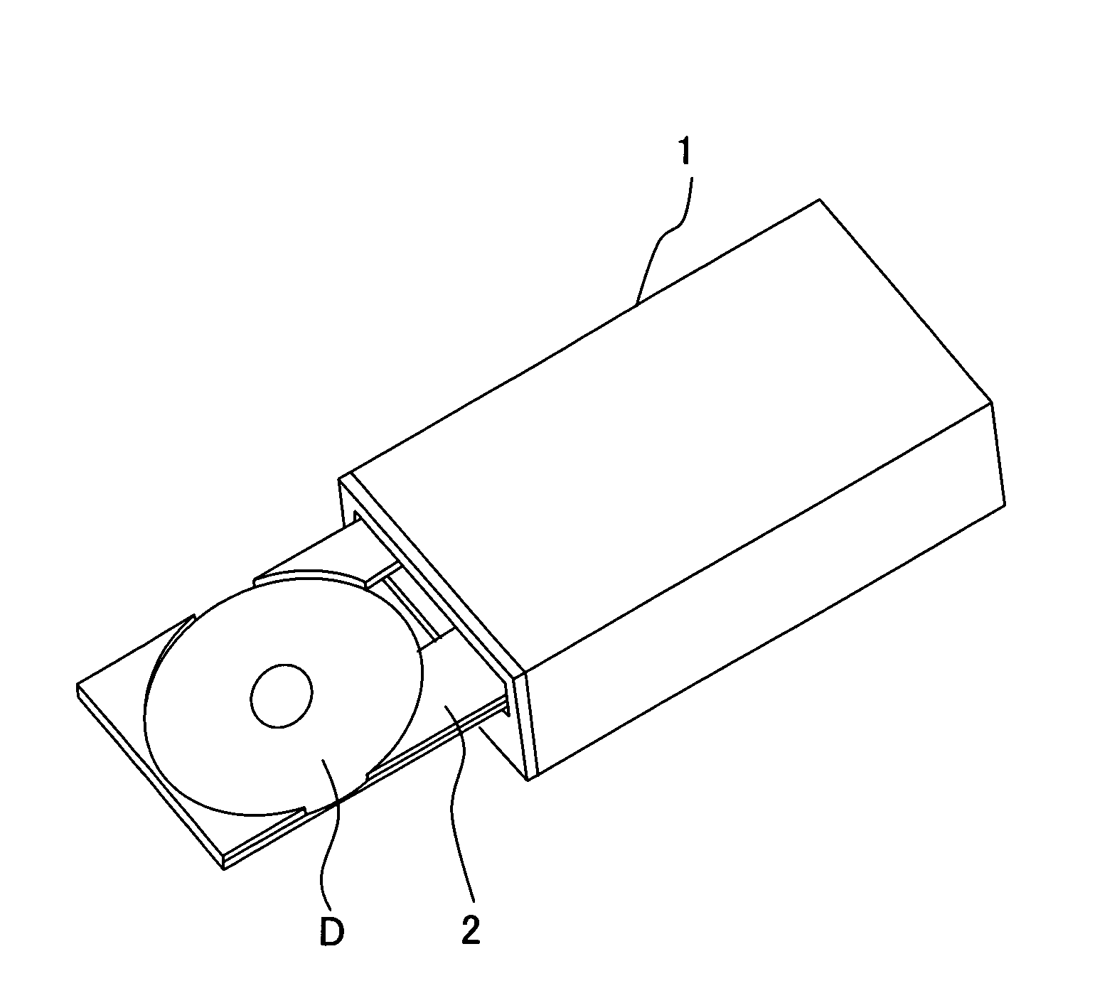
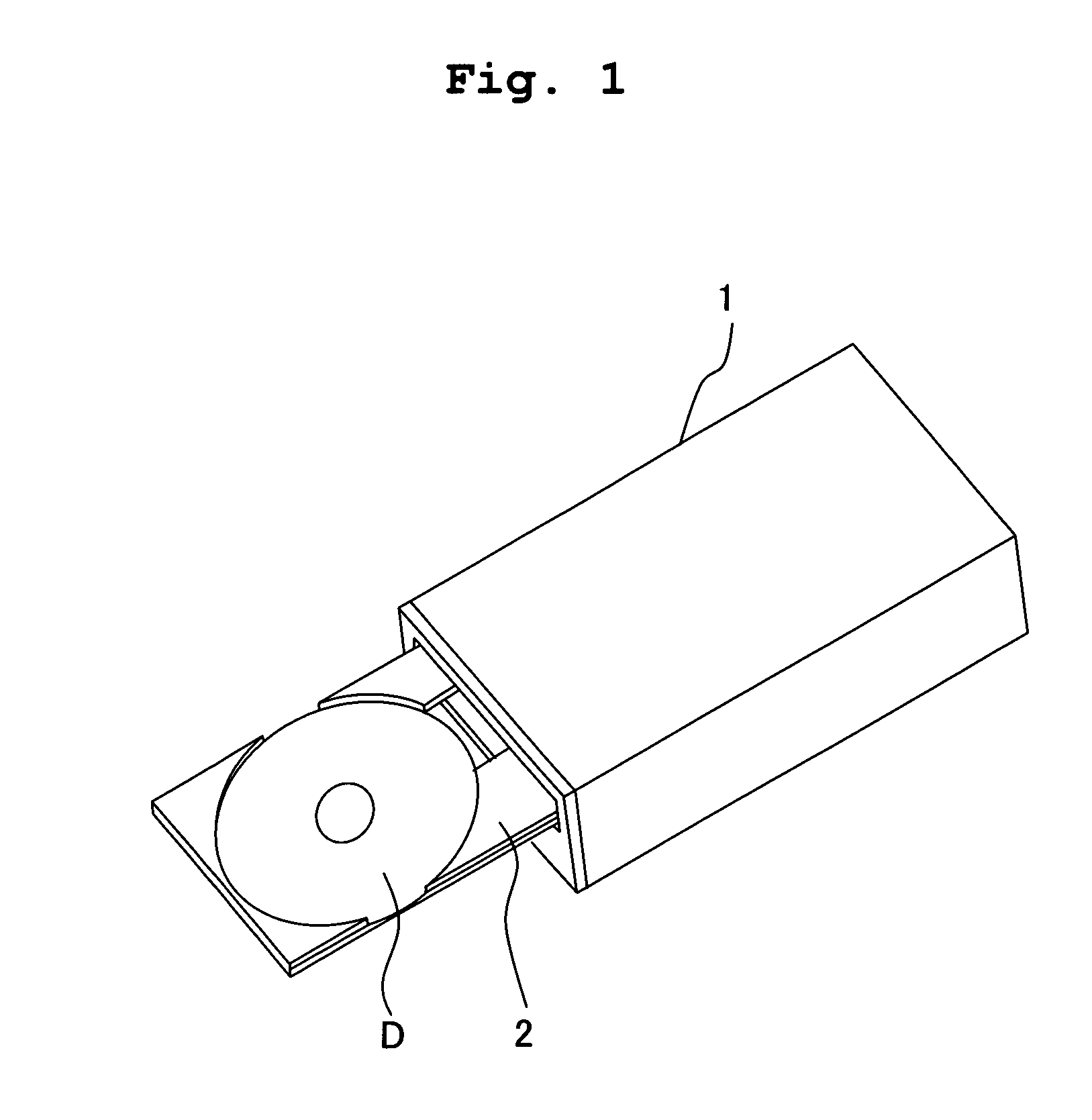
[0051]FIG. 1 is an external perspective view of a disk drive 1 (recording apparatus) according to the present embodiment. As shown in FIG. 1, the chassis of the disk drive 1 is so-called half-height size, and is the same as the chassis used an ordinary CD-ROM or CD-R / RW drive. An optical disk D as a recording medium is, for example, a CD-R, CD-RW, or the like, and has the shape of a circular plate. One of the surfaces of the optical disk D is a flat image recording surface Da (see FIG. 2) for recording an image or the like, and the other surface thereof is a flat data recording surface Db (see FIG. 2) for recording data. The disk drive 1 is a recording apparatus for recording an image on the image recording surface Da of the optical disk D and recording data on the data recording surface Db. As shown in FIG. 1, the disk drive 1 is provided with a loading tray 2 for inserting the optical disk D into the disk drive 1 or taking the optical disk D out of the disk drive 1. The optical di...

second embodiment

[0083] The second embodiment is described next. The second embodiment is different from the first embodiment in that the operation mode is not switched to the drying mode to dry the ink after recording an image on the image recording surface of the optical disk in the image recording mode.

[0084]FIG. 9 is a flowchart showing a process of the disk drive 1 when recording data and recording an image in the present embodiment. In the present embodiment, as in the case of the first embodiment, when the recording data to be recorded on the data recording surface Db of the optical disk D is input from the PC 100 to the disk drive 1, the mode switching portion 41 switches the operation mode of the disk drive 1 to the data recording mode (S200), and prepares for data recording. It should be noted that when there exists image data to be recorded on the image recording surface Da of the optical disk D in this step, this image data is also input to the disk drive 1 along with the recorded data....

modified examples

[0094] Next, modified examples in which various modifications are applied to the first and second embodiments are described. It should be noted that same reference numerals are used to indicate the portions or parts having the same configurations as these of the first and second embodiments, thus the explanations for these portions or parts are omitted as appropriate.

[0095] As shown in FIG. 10, a shielding member 71 may be inclined to a direction perpendicular to the direction of rotation of the optical disk D as viewed from direction perpendicular to the image recording surface of the optical disk (modified example 1). Specifically, the shielding member 71 may be inclined with respect to the radial direction of the optical disk D, such that an outer end portion of the shielding member 71 advances in the direction of rotation of the optical disk D. In this case, as shown in FIG. 10, some of the airflow W generated by rotating the optical disk D (airflow Wc) flows in a direction tow...


PUM

PropertyMeasurementUnit
rotation angleaaaaaaaaaa
Daaaaaaaaaaa
rotation speedaaaaaaaaaa

Abstract

To provide a recording apparatus for recording an image on a rotating recording medium, the recording apparatus including: a rotary driving unit which rotationally drives the recording medium; an ink-jet head for ejecting ink onto an image recording surface of the recording medium; and a control unit which switches between an image recording mode for ejecting ink onto the image recording surface by means of the ink-jet head while rotating the recording medium by the rotary driving unit, and a drying mode for drying the ink ejected onto the image recording surface by rotating the recording medium for a predetermined period of time by the rotary driving unit after the image recording mode. Accordingly, drying of the ink adhered to the recording medium is accelerated.

Description

BACKGROUND OF THE INVENTION [0001] 1. Field of the Invention [0002] The present invention relates to a recording apparatus and a recording method for recording an image onto a recording medium having a flat image recording surface, while rotating the recording medium. [0003] 2. Description of the Related Art [0004] As an apparatus for recording an image and the like onto an image recording surface on the side opposite to a data recording surface for recording data in a recording medium such as a CD or DVD, there is an apparatus provided with an ink-jet head which ejects ink droplets from a nozzle onto a rotating recording medium to record an image onto a disk drive which records data into the recording medium. For example, the printing apparatus disclosed in Published Japanese Translation of PCT International Publication for Patent Application No. 2002-531290 has a rotary motor for rotating a disk and an ink-jet head provided with a plurality of nozzles arranged in a row on a radial...

Claims


Application Information

Patent Timeline
Patent Type & Authority Applications(United States)
IPC IPC(8): G11B21/08
CPCB41J3/4071B41J11/002G11B19/28G11B23/40
Inventor SUGAHARA, HIROTO
Owner BROTHER KOGYO KK
Why Eureka
Try Eureka