Air-cooled turbocharger with optional internal pressure relief valve

a turbocharger and internal pressure relief technology, which is applied in the field of turbochargers, can solve the problems of complex location and installation of the turbocharger, significant cost addition to the basic turbocharger, and significant total friction loss of the complete bearing system, so as to increase the air-cooling effect and prevent the excess energy in the exhaust gas from over-speeding the turbocharger. , the effect of increasing the flow

Active Publication Date: 2014-07-22
DELGADO LAUREN N
View PDF12 Cites 13 Cited by
  • Summary
  • Abstract
  • Description
  • Claims
  • Application Information

AI Technical Summary

Benefits of technology

[0011]One preferred embodiment of the invention is a turbocharger that is self-cooled by a flow of compressed air generated by the turbocharger compressor and delivered within the turbocharger to a cooling jacket withiry the bearing housing to cool the internal structure of the turbocharger, including the turbocharger bearings. This embodiment eliminates the need for cooling fluids from outside the turbocharger, their necessary piping and conduits and associated parts and labor and possibilities of unreliable operation. Where it is desirable to do so, the flow of cooling air can be increased by the addition of a pressure relief valve that opens at a predetermined pressure level to limit the maximum speed of the turbocharger to an acceptable level and eliminate the need for an exhaust gas waste gate.
[0014]The invention can be accomplished by bleeding compressed air from the area behind the compressor wheel into the cooling jacket in the bearing housing where it can cool the internal parts of the turbocharger, and then allow the heated air to vent to the atmosphere. The air can be introduced into the bearing housing by means of simple drilled holes, leading from the area behind the compressor wheel into the cooling jacket. As the speed of the turbocharger increases, the pressure of the air behind the compressor wheel increases so that an increased flow of cooling air is bled into the bearing housing automatically to increase the air-cooling effect as exhaust temperatures increase.
[0015]The invention can also eliminate the expensive waste gates and actuation mechanisms in the hot exhaust system and employ a simple pressure relief valve in the cool part of the center section of the turbocharger to open when the compressor discharge pressure reaches a predetermined value and admit an increased amount of cooling air into the bearing housing. Compressed air is bled from the area behind the compressor wheel by small air passages (or drilled holes) that are always open or, as an alternative, can be combined with a larger pressure relief valve that communicates with the same area behind the compressor wheel. The pressure relief valve is fitted with a spring that holds the valve closed until a predetermined air charge pressure is reached. At this point, the spring force holding the relief valve closed is overcome, allowing the valve to open to admit a much larger quantity of cooling air into the cooling jacket of the turbocharger bearing housing. This additional flow of compressed air requires the turbine of the turbocharger to produce more power, which it is capable of doing, over the high speed range of the engine. Thus, in this invention, the excess energy in the exhaust gas is not discarded through a waste gate, but is used to provide the larger quantity of cooling air when the relief valve behind the compressor wheel opens. The amount of additional cooling air provided through the relief valve will absorb turbine power, and this absorption will increase as the engine speed reaches high values, thus preventing the excess energy in the exhaust gas from over-speeding the turbocharger.
[0016]The utilization of a bleed air hole and pressure relief valve is a unique method of cooling the hot internal components of a turbocharger and, concurrently, preventing the turbocharger from exceeding its maximum speed limit. This invention eliminates the conventional waste gates and the liquid cooling lines needed when engine coolant is used to cool the internal components of the turbocharger. Elimination of the waste gate and engine cooling lines results in a substantial cost saving since a simple spring-loaded relief valve is a reasonably inexpensive item.
[0017]If the air-cooled turbocharger of this invention also has a grease-lubricated bearing system, as disclosed in U.S. Pat. No. 7,025,579 B2, then the lube oil lines to and from the turbocharger are eliminated. Thus, the air-cooled, oil-less turbocharger can be remotely mounted from the engine; for example, in the vicinity of a vehicle muffler, thereby eliminating the long lube-oil lines and / or engine coolant lines to the turbocharger and back from the turbocharger to the engine. This amounts to another substantial cost saving as a result of implementing this invention.
[0018]Additionally, the air bleed hole and relief valve combination of this invention can be easily designed into a turbocharger that has a bearing system using engine lubricating oil, as disclosed in U.S. Pat. No. 7,677,041 B2, if it has a cooling jacket in the bearing housing. It would be implemented in the same manner as illustrated in FIG. 1 and FIG. 2.

Problems solved by technology

The friction loss associated with the thrust bearing, plus the friction losses in the inner and outer oil films of the floating sleeve bearings, results in a substantial total friction loss for the complete bearing system.
In applications where such cooling of the bearings is required, the location and installation of the turbocharger is complicated and made more expensive by the requirement for piping for the engine lubricant and / or engine coolant between the turbocharger and the internal combustion engine.
The waste gate valve and its operating mechanism represent a significant cost addition to the basic turbocharger.
Notwithstanding years of turbocharger design, development and production, the use of turbochargers remains complicated by their need for cooling of the internal parts of the turbocharger, including the bearings that carry the rotating assembly of the turbocharger and are heated, not only by the friction losses of the bearings themselves, but also by the heat conducted through the rotating shaft from the turbine wheel, which is exposed to the hot exhaust gases of the internal combustion engine.

Method used


Image

  • Air-cooled turbocharger with optional internal pressure relief valve
  • Air-cooled turbocharger with optional internal pressure relief valve
  • Air-cooled turbocharger with optional internal pressure relief valve

Examples


Embodiment Construction

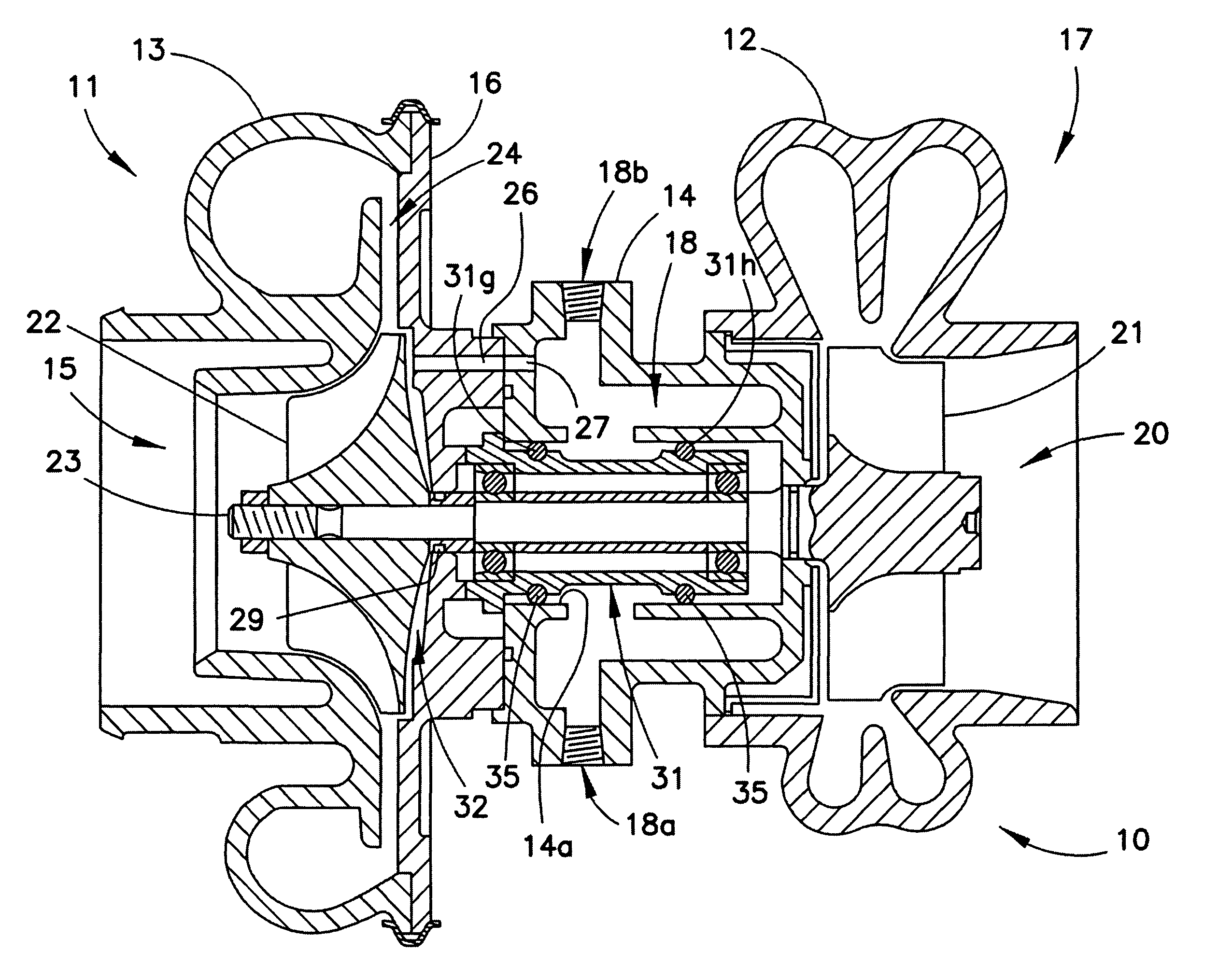
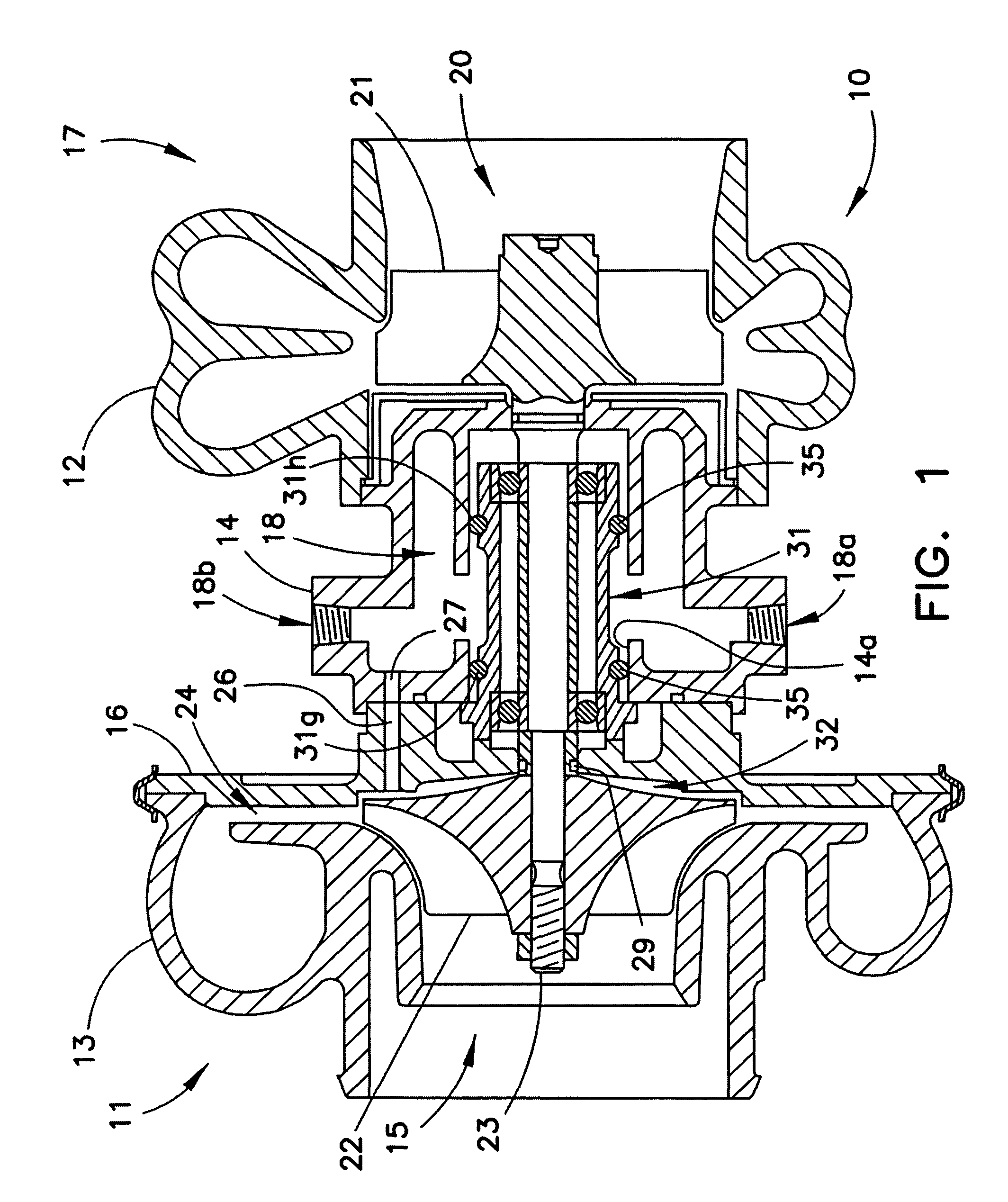
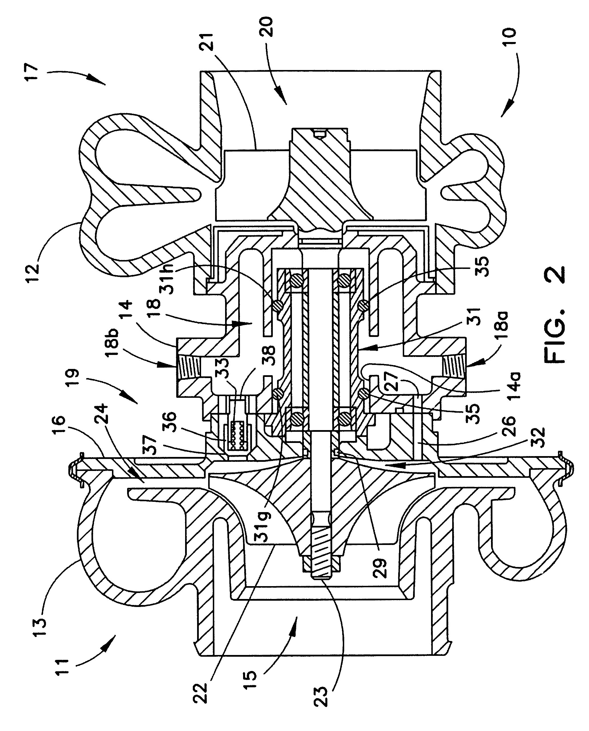
[0023]As noted above, the invention provides an air-cooled turbocharger, which may, in a preferred embodiment be self-cooled. FIG. 1 illustrates a self-cooled embodiment of the invention where a flow of compressed air from compressor 11 is provided through a compressed air conduit 26,27 to a cooling jacket 18 of the turbocharger bearing housing 14. FIG. 2 also illustrates a self-cooled embodiment of the invention which includes, in addition to a compressed air conduit 26, 27, a pressure relief valve 19, which can open at a predetermined pressure within compressor 11 to initiate a larger flow of compressed air into the bearing housing cooling jacket. As illustrated in FIGS. 1 and 2 the self-cooled turbocharger of the invention includes an exhaust-driven turbine 17 for driving a rotatable shaft 23, a compressor wheel 22 driven by the rotatable shaft 23 for generating a flow of compressed air for delivery from the compressor casing 13 to the cylinders of an internal combustion engine (...


PUM


Abstract

A cooling system for a turbocharger that has a cooling jacket in the bearing housing wherein air is bled from the area behind the compressor wheel and introduced into the cooling jacket, through which it circulates and then exits into the atmosphere. In addition, a pressure relief valve located behind the compressor wheel is set to open at a predetermined charge air pressure level to introduce additional cooling air into the cooling jacket and also acts to limit the maximum rotational speed of the turbocharger over the high-speed range of the engine on which the turbocharger is mounted. In an alternate embodiment of the invention, cooling air can be taken from the intake manifold system of a turbocharged engine downstream of an air-to-air aftercooler and ducted to the cooling jacket in the turbocharger bearing housing.

Description

FIELD OF THE INVENTION[0001]This invention relates to turbochargers used on internal combustion engines, and more particularly to turbochargers in which the bearings that carry the rotating parts of the turbocharger need cooling.BACKGROUND OF THE INVENTION[0002]Turbochargers that are used on both diesel and gasoline engines to increase power output, reduce fuel consumption and reduce emissions have reached an advanced stage of development. The higher mileage and emission standards set by the Obama administration, which begin to take effect in 2012 and are to be achieved by 2016, will necessitate changes to the American car and truck fleet. Passenger cars will be required to get 39 miles per gallon, and light trucks to get 30 miles per gallon. Some U.S. car manufacturers are already taking advantage of turbochargers to help achieve these goals. A news release announced in May of 2009, that Ford Motor Company had started producing its EcoBoost V-6 turbocharged engine, said to boost fu...

Claims


Application Information

Patent Timeline
Patent Type & Authority Patents(United States)
IPC IPC(8): F01D25/22F01D5/08F01D25/12F02C6/12
CPCF01D25/12F01D5/087F01D5/082F02C6/12F05D2260/52
Inventor WOOLLENWEBER, WILLIAM, E.
Owner DELGADO LAUREN N
Why Eureka
Try Eureka