Method for detecting the position of a rotor of a DC motor and related circuit

a dc motor and related circuit technology, applied in the field of detecting the position of the rotor of the dc motor and the related circuit, can solve the problems of increasing the number of pins of the integrated circuit, bulky printed circuit boards, increasing the associated cost, etc., to achieve greater voltage, improve the performance of the motor, and eliminate external resistance

Inactive Publication Date: 2005-01-11
STMICROELECTRONICS SRL
View PDF12 Cites 12 Cited by
  • Summary
  • Abstract
  • Description
  • Claims
  • Application Information

AI Technical Summary

Benefits of technology

Thanks to the present invention it is possible to determine the position of a rotor of a DC motor while eliminating the external resistance and therefore improving the performances of the motor. Particularly, in the absence of any voltage drop on the resistance, it is possible to supply a greater voltage to the motor and therefore a greater starting current and a greater maximum speed, with a lower total dissipated power.

Problems solved by technology

The value of the resistance varies normally from 100 milliohms to 500 milliohms and cannot be integrated inside of the integrated circuits and therefore it is placed outside with consequent increasing of the number of pins of the integrated circuit, bulk on the printed circuit board and increasing of the associated cost.
Besides, the resistance causes a limit on the maximum voltage that can be furnished to the motor and has a not negligible power dissipation.

Method used


Image

  • Method for detecting the position of a rotor of a DC motor and related circuit
  • Method for detecting the position of a rotor of a DC motor and related circuit
  • Method for detecting the position of a rotor of a DC motor and related circuit

Examples


Embodiment Construction

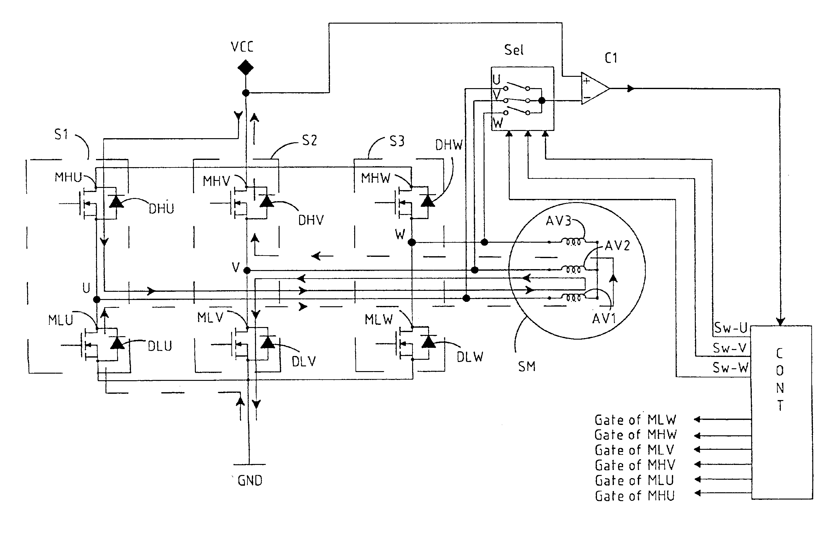
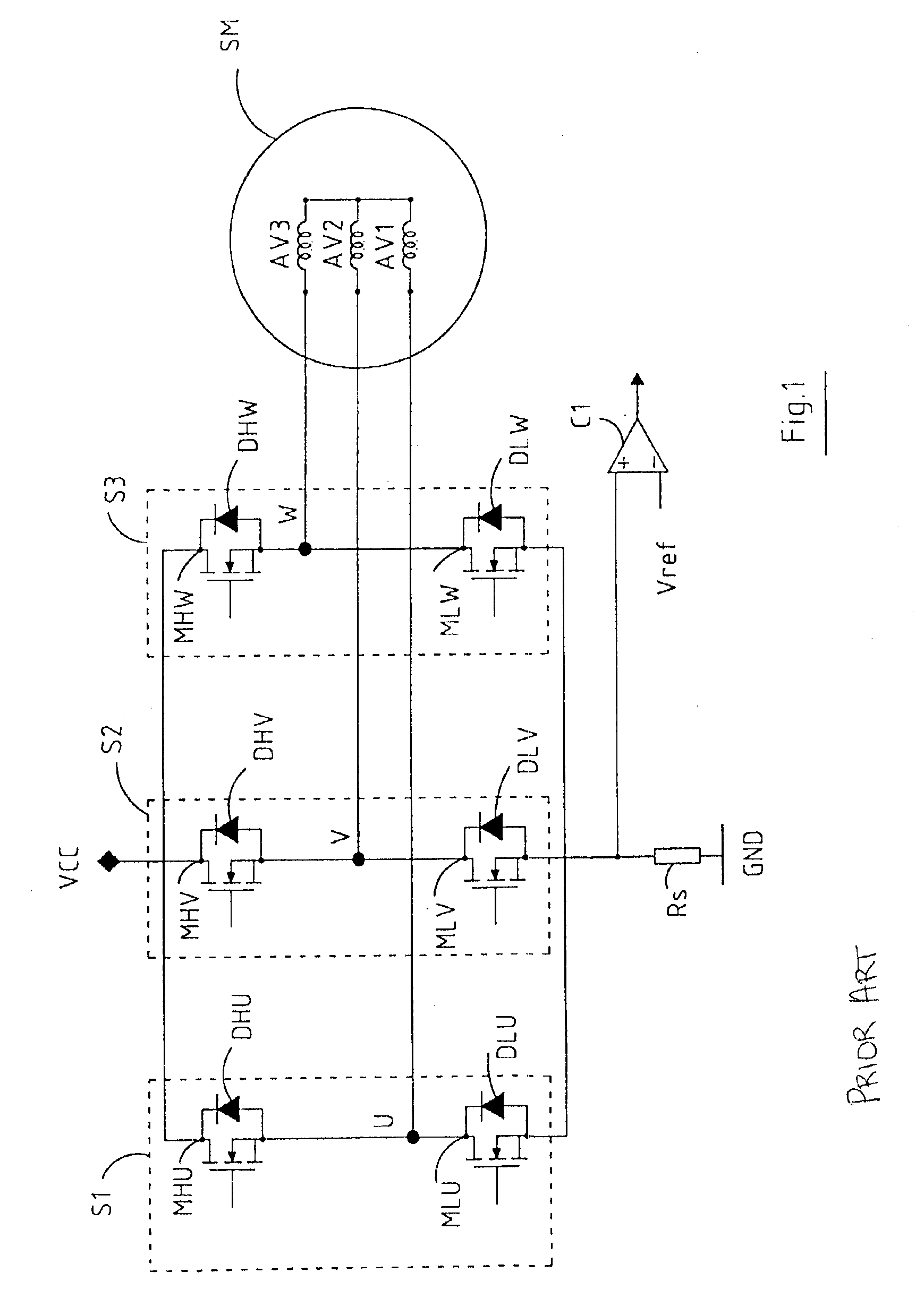
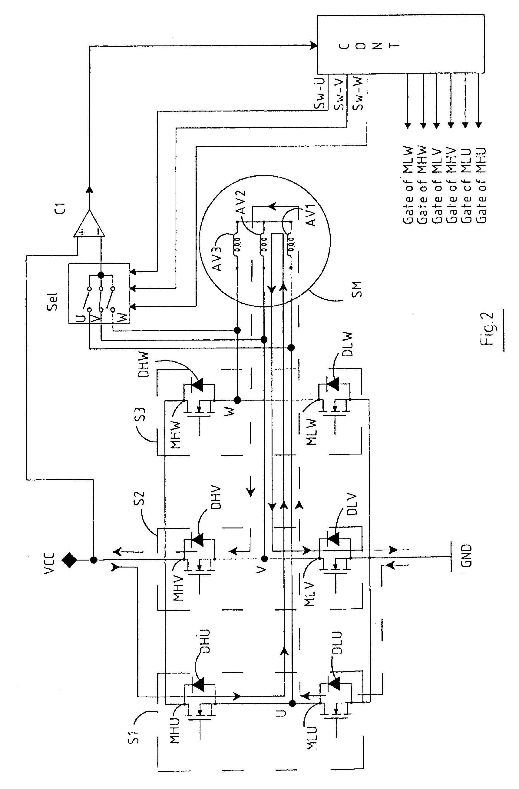
In FIG. 1, which represents the partial scheme of a driving circuit of a three-phase motor according to the known art, there are three substantially identical driving circuits at half-bridge S1, S2, and S3. Each of the half-bridges is constituted by a high side transistor and a low side transistor, each one with the associated reflow diode, respectively indicated with MHU, MLU and DHU, DLU for the half-bridge S1; MHV, MLV and DHV, DLV for the half-bridge S2; and MHW, MLW and DHW, DLW for the half-bridge S3. The high side transistors have their drains connected to the positive supply voltage Vcc, the low side transistors have their sources connected together and connected to the ground Gnd through a resistance Rs. The source of each high side transistor is connected to the drain of each low side transistor. The point of connection of the half-bridge S1 corresponds to the U phase and is connected to a terminal of the winding AV1, the point of connection of the half-bridge S2 correspon...


PUM

PropertyMeasurementUnit
resistanceaaaaaaaaaa
voltageaaaaaaaaaa
voltageaaaaaaaaaa

Abstract

A method for detecting the position of a rotor of a DC motor with N phases having a plurality of windings, comprising the steps of connecting two of the windings between first and second prefixed voltages through to a first current path for a prefixed time, allowing the current stored in the two windings to discharge through a second current path; comparing the voltage across one of the two windings with a reference voltage and providing a control signal when the voltage is smaller in absolute value than the reference voltage, performing the above steps for each of the winding pairs of the motor; detecting the position of the rotor on the basis of the control signals obtained.

Description

BACKGROUND OF THE INVENTION1. Field of the InventionThe present invention refers to a method for detecting the position of a rotor of a DC motor and to the related circuit.2. Description of the Related ArtA DC motor comprises a permanent magnet that constitutes the rotor and a stator having a plurality of windings. This type of motor is commonly used to operate computer hard disks, DVDs (Digital Video Disk), CDs etc.In most cases, DC motors have three phases and the driving circuit generally comprises integrated circuits whose output stages, typically half-bridges, drive the windings cyclically.For the starting of a DC motor it is necessary to supply the windings in the correct combination of phases, and in order to do so it is necessary to know the position of the rotor.The detection of the position of the rotor is based normally on the fact that the winding impedance depends on the position of the rotor. For this reason a small current is provided sequentially in each of the combi...

Claims


Application Information

Patent Timeline
Patent Type & Authority Patents(United States)
IPC IPC(8): G11B19/20H02P6/00H02P6/22H02P6/18H02P6/14H02P6/182H02P6/185
CPCG11B19/20H02P6/22H02P6/185H02P6/182
Inventor BOSCOLO, MICHELEBRAMBILLA, MASSIMILIANOGALBIATI, EZIO
Owner STMICROELECTRONICS SRL
Why Eureka
Try Eureka