System and method for reducing second order distortion in electronic circuits

a second-order distortion and electronic circuit technology, applied in the direction of amplifier modification, amplifier details, differential amplifiers, etc., can solve the problems of second-order distortion in electronic circuits, variable resistors are dominant sources of second-order distortion, etc., and achieve the effect of significantly reducing the modulation of resistan

Inactive Publication Date: 2005-05-10
CSR TECH INC
View PDF6 Cites 7 Cited by
  • Summary
  • Abstract
  • Description
  • Claims
  • Application Information

AI Technical Summary

Benefits of technology

[0003]It has been found that a primary cause of second order distortion in electronic circuits, and particularly in differential amplifiers, is due to signal imbalances. These imbalances can be either mismatches within the circuit itself or could be caused by imbalances in the applied input signal. In one embodiment, concepts of the present invention are applied to a variable gain amplifier which has its gain adjusted under control of an adjustment signal applied to one input of the amplifier. The adjustment signal may be provided, for example, through use of a variable resistor whose value is controlled by an externally applied gain control signal. It has been determined that such a variable resistor is a dominant source of second order distortion because the value of the resistor changes based on the input signals. By taking what is essentially the average voltage of the input signals, and injecting that average (or a fraction of that average) into the variable resistor adjustment signal, the modulation of the resistance can be significantly reduced.

Problems solved by technology

It has been found that a primary cause of second order distortion in electronic circuits, and particularly in differential amplifiers, is due to signal imbalances.
These imbalances can be either mismatches within the circuit itself or could be caused by imbalances in the applied input signal.
It has been determined that such a variable resistor is a dominant source of second order distortion because the value of the resistor changes based on the input signals.

Method used


Image

  • System and method for reducing second order distortion in electronic circuits
  • System and method for reducing second order distortion in electronic circuits

Examples


Embodiment Construction

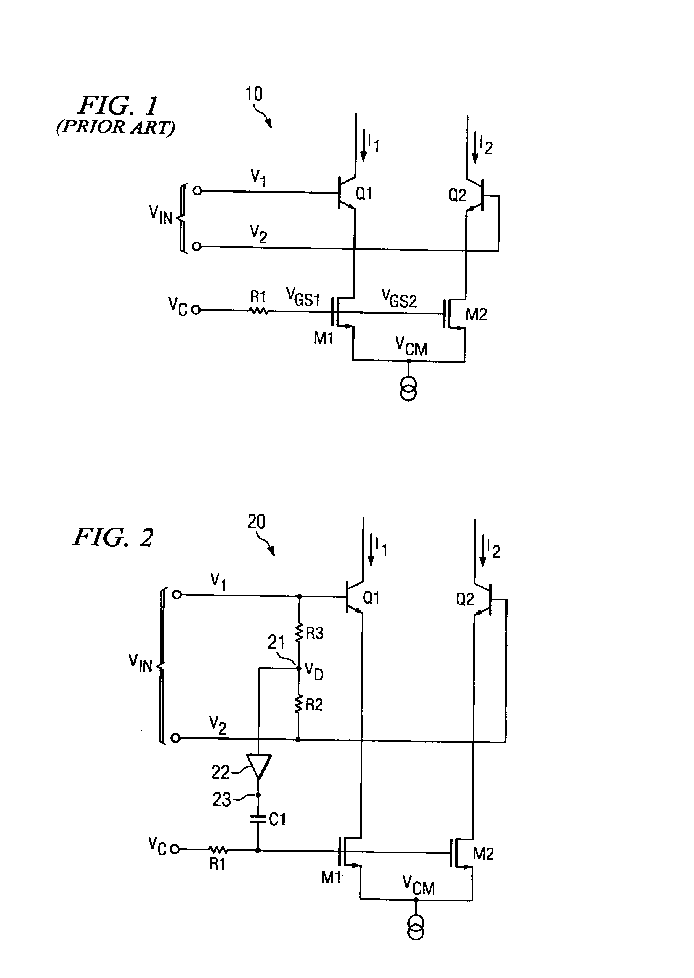
[0008]FIG. 1 is a simplified diagram of the input stage of prior art gain-controlled differential amplifier 10. Input voltages at VIN (such as differential input voltages V1 and V2) are converted into currents I1 and I2. M1 and M2 are variable resistors where the resistance depends on the gate voltage for each device (VGS1 and VGS2, respectively). This voltage is equal to VC minus VCM. Any input signal (V1, V2) imbalance coming into transistors Q1 and Q2 of circuit 10 translates to a voltage VCM that varies depending on the input voltage. As a result of this variation in the voltage VCM, the voltage differential (VC−VCM) also varies, causing the resistance of M1 and M2 to change. This resistance change causes problems in the signal processing circuit, such as second order distortion.

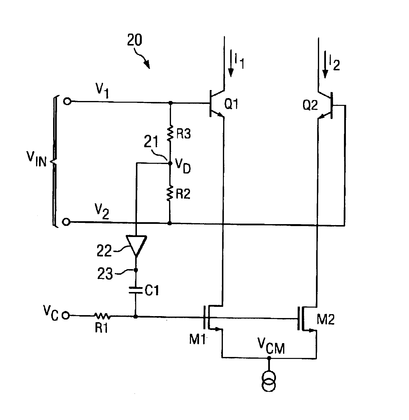
[0009]As shown in FIG. 1, devices M1 and M2 are part of the degeneration network of the amplifier. When the input signal, VIN, is balanced (i.e., VI =VIN (common mode)+Vd / 2 and V2=VIN (common mode )−Vd / 2...


PUM


Abstract

System and methods for reducing the effects of imbalance between input signals in a gain controlled differential amplifier are shown. Distortion in the amplifier is reduced by modulating the gain control input based upon detected differences between the signal levels of the differential input signal source.

Description

TECHNICAL FIELD[0001]This invention relates in general to reducing second order distortion in electronic circuits more particularly to systems and methods for reducing the effects imbalances between differential input signals to gain-controlled amplifier circuits.BACKGROUND[0002]One method of reducing second order distortions in electronic circuitry is to use a differential amplifier. In order to use a differential amplifier there must be differential (at least two) signals coming into the amplifier circuitry. Unfortunately, differential signals do not usually come to a circuit from external sources. The signals that typically arrive at a device from external sources are single-ended signals. A balun, which is a balance transformer, converts the single-ended signal to a differential signal. Baluns are relatively expensive, have bulk and do not always provide a balanced output. In some instances, the output of the balun is not fully differential. These “non perfect” balun outputs the...

Claims


Application Information

Patent Timeline
Patent Type & Authority Patents(United States)
IPC IPC(8): H03F3/45
CPCH03F3/4556
Inventor PATEL, GIRISHDOUGLASS, JAMES M.
Owner CSR TECH INC
Why Eureka
Try Eureka