Protective device for protecting a transformer against geomagnetically induced currents

a protection device and transformer technology, applied in the field of electric transformers, can solve the problems of serious faults in the operating characteristics of transformers, adversely affecting the service life of the electrical winding of the transformer, unacceptably high heating, etc., and achieve the effect of long service life and reliable protection against gi

Inactive Publication Date: 2017-06-15
SIEMENS AG
View PDF4 Cites 3 Cited by
  • Summary
  • Abstract
  • Description
  • Claims
  • Application Information

AI Technical Summary

Benefits of technology

[0013]It is therefore an object of the present invention to provide a protective device for a transformer, by which the transformer can be reliably protected against GIC in the simplest manner possible and over a long service life.

Problems solved by technology

It is well known that electrical transformers as routinely used in energy transmission and distribution networks can be exposed to Geomagnetically Induced Currents (GIC), which can exceed 100 A and cause serious faults in the operating characteristics of transformers.
These higher frequency components in the flux leakage field result in increased eddy-current losses in the metallic parts of the transformer and changed current distribution in the windings of the transformer, which can cause unacceptably high heating locally.
Increased heating adversely affects the service life of the electrical winding of the transformer, and cracked gases can occur due to thermal decomposition of the insulating fluid.
A further problem can arise if the high reactive power absorption also causes an unacceptably high voltage drop or if a protective device responds incorrectly due to the harmonics, and therefore GIC current flow can lead to a blackout in the energy distribution network in the worst case.
However, the GIC current flow also results in increased noise emission, this being particularly disadvantageous if the transformer is installed in the vicinity of a residential area.
In order to protect the capacitor against overcurrent or overvoltage, sophisticated protective devices are required at considerable expense.
It is also disadvantageous that a GIC blocker can only protect the transformer between whose neutral point and ground it is connected.
A further disadvantage arises in the case of autotransformers, in that such GIC blockers cannot readily be used because there is no electrical isolation between primary and secondary sides.
Using existing protective devices, these high GIC currents can only be managed at significant expense.

Method used


Image

  • Protective device for protecting a transformer against geomagnetically induced currents
  • Protective device for protecting a transformer against geomagnetically induced currents
  • Protective device for protecting a transformer against geomagnetically induced currents

Examples


Embodiment Construction

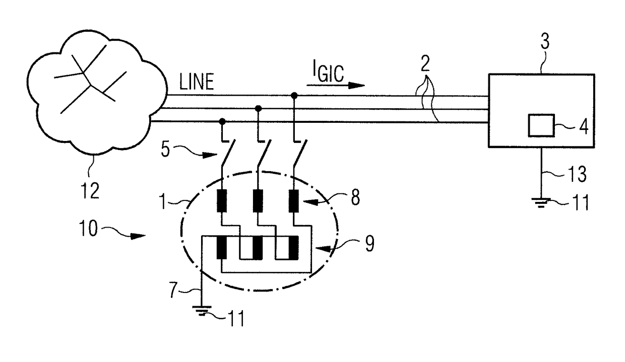
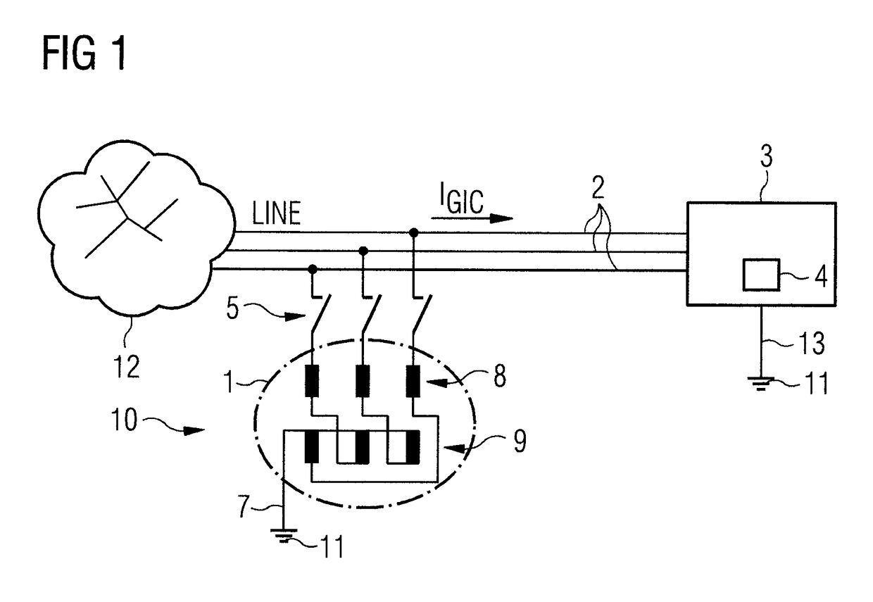
[0031]FIG. 1 shows a connection diagram of a first exemplary embodiment of the invention in a simplified illustration. The reference sign 10 designates the overall protective device. This consists essentially of a grounding transformer 1, which connects the three phases of the supply lines 2 (LINE) to a transformer 4 having ground potential 11. The transformer 4 is housed in a transformer substation 3.

[0032]In an energy supply network 12, the electrical energy is transformed from a high-voltage network (750-110 kV) to a medium-voltage network, or from a medium-voltage network (e.g., 10-30 kV) to a low-voltage network (secondary distribution network having a voltage of, e.g., 400 V / 230 V), in a transformer substation 3, also known as a transformer station, distribution station or distribution substation. A transformer substation 3 contains at least one transformer with corresponding switching systems for the medium-voltage network and low-voltage network, and protective devices.

[0033...


PUM

PropertyMeasurementUnit
currentaaaaaaaaaa
GIC currentsaaaaaaaaaa
voltageaaaaaaaaaa

Abstract

A protective device for a transformer which is connected on the high-voltage side via supply lines to a network for transmission and distribution of electrical energy, wherein the transformer includes a neutral grounding, where each supply line is connected to ground via a grounding transformer , and where the grounding transformer includes a neutral point resistance which is lower than the neutral point resistance of the neutral grounding, such that Geomagnetically Induced Current flowing on the supply lines is diverted to ground.

Description

BACKGROUND OF THE INVENTION[0001]1. Field of the Invention[0002]The invention relates generally to the technical field of electrical transformers and, more particularly, to a protective device for a transformer which is connected on the high-voltage side by via supply lines to a network for the transmission and distribution of electrical energy, where the transformer has a neutral grounding.[0003]2. Description of the Related Art[0004]It is well known that electrical transformers as routinely used in energy transmission and distribution networks can be exposed to Geomagnetically Induced Currents (GIC), which can exceed 100 A and cause serious faults in the operating characteristics of transformers.[0005]A GIC is caused by strong solar winds that produce a temporal change in the Earth's magnetic field. If this temporal change in the Earth's magnetic field passes through a conductor loop (consisting of, e.g., a line section of the energy distribution network and the ground as a return...

Claims


Application Information

Patent Timeline
Patent Type & Authority Applications(United States)
IPC IPC(8): H02H7/04H01F27/28
CPCH01F27/28H02H7/04H02H9/02H01F27/38
Inventor HAMBERGER, PETER
Owner SIEMENS AG
Why Eureka
Try Eureka