
Mailing envelope assembly

a technology for mailing envelopes and assembly parts, applied in the direction of packaging, transportation and packaging, paper/cardboard containers, etc., can solve the problems of high waste, high capital expenditure, and high production cost of standard mailing envelope assemblies

Inactive Publication Date: 2005-05-17
SLEEPECK PRINTING
View PDF35 Cites 16 Cited by
  • Summary
  • Abstract
  • Description
  • Claims
  • Application Information

AI Technical Summary

Benefits of technology

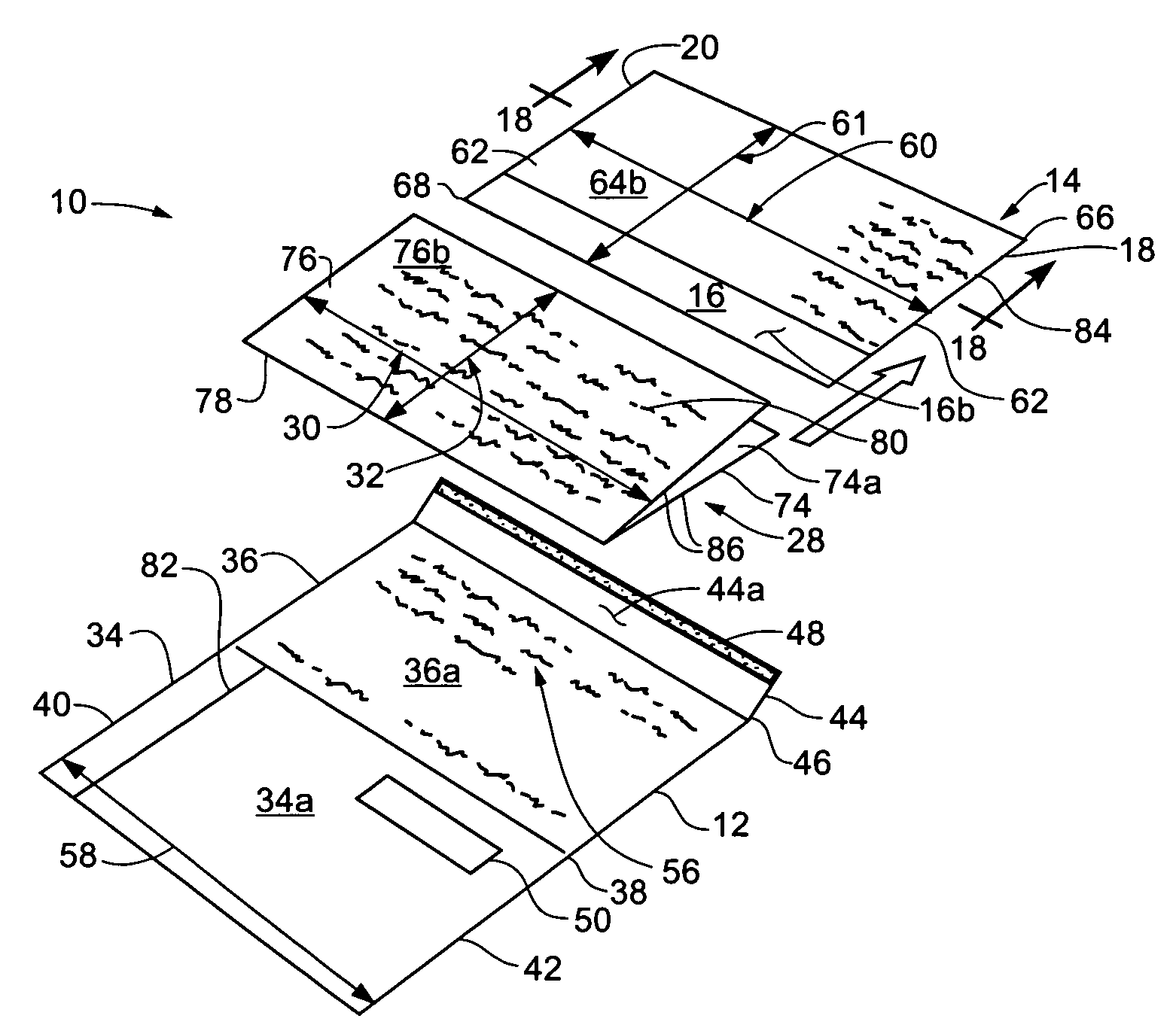
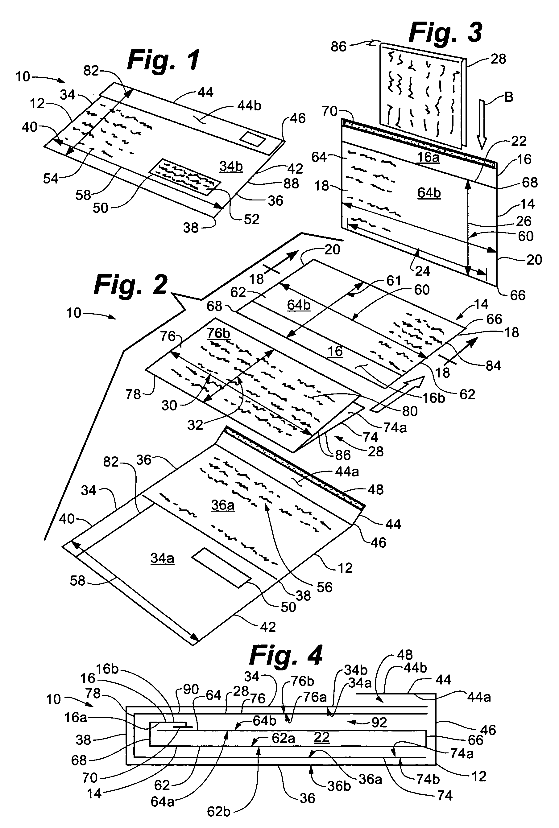
[0005]In accordance with one aspect of the present invention, a mailing envelope assembly is provided that includes a foldable insert that fits into an inner envelope after it is transversely folded in half and rotated 90° relative to its orientation as contained in an outer envelope. The assembly includes an outer envelope that typically will be sealed and an inner envelope and foldable insert contained within the outer envelope. The inner envelope typically has a flap, closed ends and an interior portion that has an interior or usable longitudinal length and an interior or usable transverse width. The foldable insert is contained within the outer envelope, typically in a desired orientation, and typically has a longitudinal length as contained in the outer envelope that is greater than the interior longitudinal length (i.e., the usable longitudinal interior) of the inner envelope, the longitudinal length of the insert as contained in the outer envelope being no greater than twice the interior or usable transverse width of the inner envelope and the insert having a transverse width as contained in the outer envelope that is no greater than the interior longitudinal length of the interior portion of the inner envelope. The foregoing relationships of the insert and inner envelope allow the insert to fit inside the inner envelope after it is transversely folded in half and rotated 90°.

Problems solved by technology

The manufacture of standard mailing envelope assemblies can be capital intensive from an equipment acquisition standpoint and often produces a higher amount of waste than desired.

Method used


Image

  • Mailing envelope assembly
  • Mailing envelope assembly
  • Mailing envelope assembly

Examples


first embodiment

[0054]Outer envelope 12, inner envelope 14 and insert 28 of sealed assembly 10 may be attached to each other or loose and held in place by frictional engagement. In addition, inner envelope 14 and insert 28 may be assembled in assembly 10 in many different manners. In a first embodiment, outer envelope 12, inner envelope 14 and insert 28 are not attached, as illustrated in FIG. 4. Inner envelope 14 is nested within insert 28, and specifically, fold 68 of inner envelope 14 is nested within fold 78 of insert 28. Insert 28 is nested within outer envelope 12, and specifically, fold 78 of insert 28 is nested within fold 38 of outer envelope 12. In this embodiment, optional glue dots 90 and 92 may be added to further ensure the sealing of outer envelope 12 and assembly 10 as a whole. In one preferred embodiment, glue dots 90 and 92 are spots or beads of pressure-sensitive adhesive.

[0055]In the first embodiment, interior surface 34a of front panel 34 of outer envelope 12 is adjacent to ext...

second embodiment

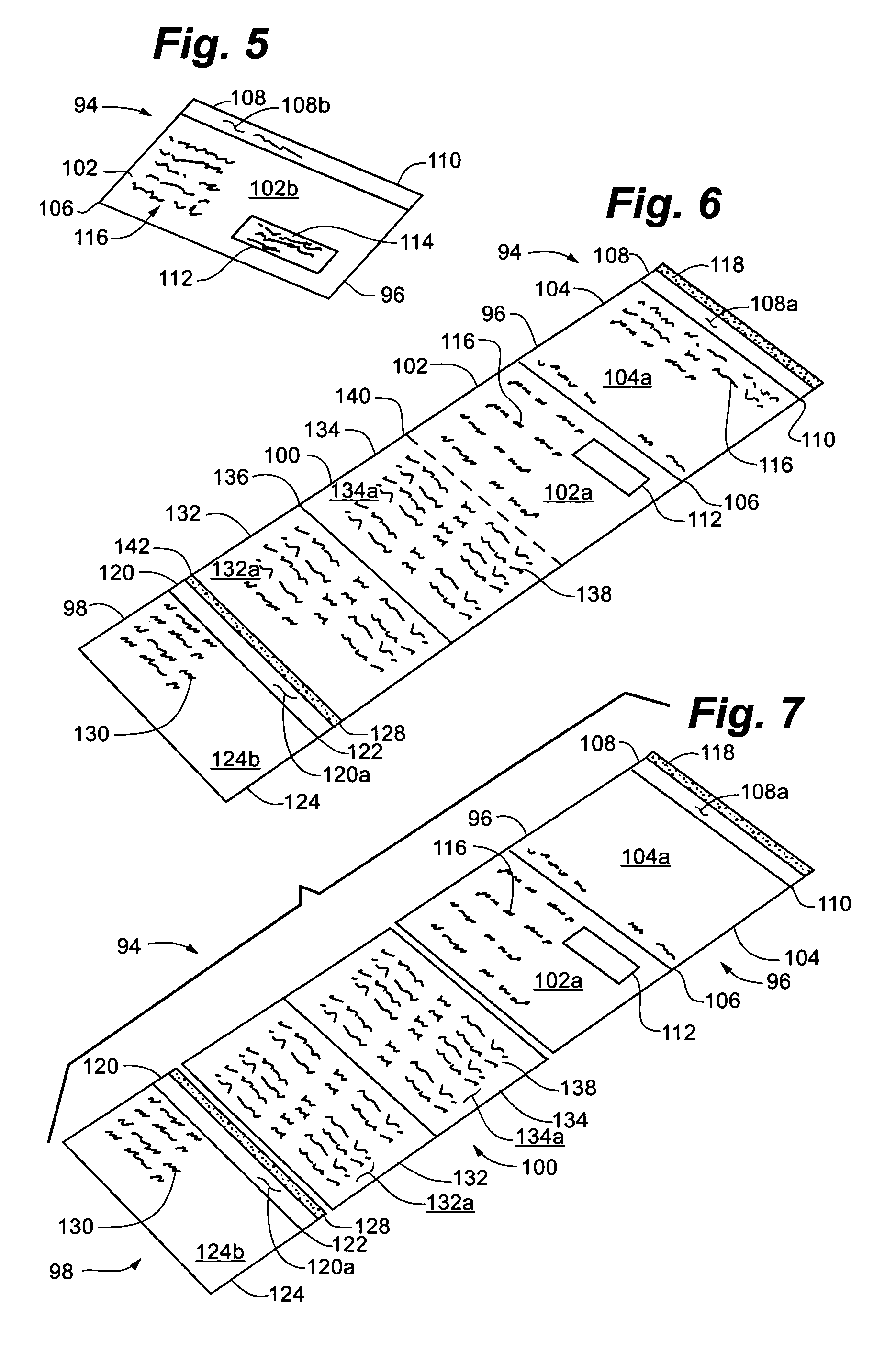
[0056]assembly 94 is illustrated in FIGS. 5–8 in which outer envelope 96, inner envelope 98 and insert 100 are attached to each other. Outer envelope 96 includes a front panel 102 and a rear panel 104, formed by fold 106, and a flap 108, formed by fold 110. Front panel 102, rear panel 104 and flap 108 include interior surfaces, 102a, 104a and 108a, respectively, and exterior surfaces 102b, 104b and 108b, respectively. Outer envelope 96 may further include a die cut window 112 for a mailing address 114 and indicia 116 on exterior surface 102b of front panel 102 and interior surfaces 102a of front panel 102 and 104a of rear panel 104. Outer envelope 96 further includes adhesive material 118 on interior surface 108a of flap 108. Inner envelope 98 includes a flap 120 formed by fold 122, a front panel 124 and a rear panel 126. Flap 120, front panel 124 and rear panel 126 include interior surfaces 120a, 124a and 126a, respectively, and exterior surfaces 120b, 124b and 126b, respectively. ...

third embodiment

[0058]assembly 144 is illustrated in FIG. 9 in which outer envelope 146, inner envelope 148 and insert 150 are not attached to each other and are instead held in place by frictional engagement. Outer envelope 146 includes a front panel152 and a rear panel 154, both formed by fold 156, and a flap 158, formed by fold 160. Front panel 152, rear panel 154 and flap 158 include interior surfaces 152a, 154a and 158a, respectively, and exterior surfaces 152b, 154b and 158b, respectively. Outer envelope 146 further includes adhesive material 162 on interior surface 158a of flap 158. Inner envelope 148 includes a front panel 164 and a rear panel 166, formed by fold 168, and a flap 170, formed by fold 172. Front panel 164, rear panel 166 and flap 170 include interior surfaces 164a, 166a and 170a, respectively, and exterior surfaces 164b, 166b and 170b, respectively. Inner envelope 148 further includes adhesive material 174 on interior surface 170a of flap 170. Insert 150 includes four panels, ...


PUM

PropertyMeasurementUnit
Angleaaaaaaaaaa
Lengthaaaaaaaaaa
Adhesion strengthaaaaaaaaaa

Abstract

A mailing envelope assembly is disclosed. The assembly includes a sealed outer envelope. The assembly further includes an inner envelope contained within the outer envelope. The inner envelope has a flap, closed ends and an interior portion. The interior portion has an interior longitudinal length and an interior transverse width. The assembly still further includes a foldable insert that is contained and oriented within the outer envelope. The insert typically has a longitudinal length as contained in the outer envelope that is greater than the interior longitudinal length of the inner envelope. The longitudinal length of the insert as contained in the outer envelope is no greater than twice the interior transverse width of the inner envelope. The insert also has a longitudinal length as contained in the outer envelope that is no greater than twice the interior or usable transverse width of the interior portion of the inner envelope, so that when the insert is transversely folded in half and rotated 90° relative to the orientation of the insert as contained in the outer envelope, the folded insert fits within the interior portion of the inner envelope.

Description

TECHNICAL FIELD[0001]The present invention relates to a mailing envelope assembly that is particularly suitable for mass mailings. More particularly, the present invention relates to a mailing envelope assembly with a sealed outer envelope, an inner envelope and an insert, with both the inner envelope and insert contained within the sealed outer envelope.BACKGROUND OF THE INVENTION[0002]A need exists for a mailing envelope assembly product that can be suitable for mass mailings and that qualifies for and can meet the United States Postal regulations for automated bulk or minimum mailing rates. A need exists for a mailing envelope assembly that qualifies for, for example, but is not limited to, “automated mail” and “letter size” regulations.[0003]Businesses that send mailing envelope assemblies typically desire to obtain a response from the recipients. Recipients, on the other hand, often do not wish to be bothered by mail solicitations. In order to achieve a higher probability that ...

Claims


Application Information

Patent Timeline
IPC IPC(8): B31B1/90B31B1/74B42D5/02
CPCB42D5/025
Inventor DAHLQUIST, AKE L.
Owner SLEEPECK PRINTING
Learn More