Compression set packer and method of use

a compression set and packer technology, applied in the field of downhole packers, can solve the problems of difficult to select one tool at a time, difficult to determine whether, and difficult to run other downhole tools

Inactive Publication Date: 2005-05-24
SPECIALISED GASOLINEEUM SERVICES GROUP
View PDF21 Cites 30 Cited by
  • Summary
  • Abstract
  • Description
  • Claims
  • Application Information

AI Technical Summary

Benefits of technology

[0009]According to a first aspect of the present invention there is provided a packer tool for mounting on a work string, wherein the packer tool comprises a body with one or more packer elements and a sleeve, wherein the sleeve has or is associated with a shoulder and is movable in relation to the tool body, wherein the shoulder co-operates with a formation, wherein upon co-operation with the formation, the sleeve can be moved relative to the tool body by setting down weight on the tool, and wherein movement of the sleeve relative to the tool body compresses the one or more packer elements.

Problems solved by technology

It is normally difficult to determine whether there are any irregularities in the well bore casing connections and cement bonds as the hydrostatic pressure created by drilling fluid within the well bore prevents well bore fluid from entering the annulus of the bore.
A disadvantage with conventional packer tools lies in the fact that they are usually set by a relative rotation within the well bore.
It is therefore difficult to run other downhole tools which are also set by rotation methods, for example in J-slots, on the work string containing the packer, at the same time as it is difficult to selectively activate one tool at a time.
Rotation of the work string in order to activate a well clean up tool or reamer would set the packer prematurely.
A further disadvantage with conventional packer tools is that they tend to have large outer diameters.
This limits the bypass for circulation of fluid through the well bore and the tool itself when the packer is not set, thereby detrimentally affecting lubrication of the tool and removal of any debris or cuttings from the bore.
Furthermore, the fluid circulating around a packer tool within a well bore is often at very high speed due to the limited by pass area.
As the only passage for fluid is between the external surface of the packer and the internal surface of the well bore in conventional packer tools, a high flow rate may damage the individual packer elements which are typically located on the external surface of the tool.

Method used


Image

  • Compression set packer and method of use
  • Compression set packer and method of use
  • Compression set packer and method of use

Examples


Embodiment Construction

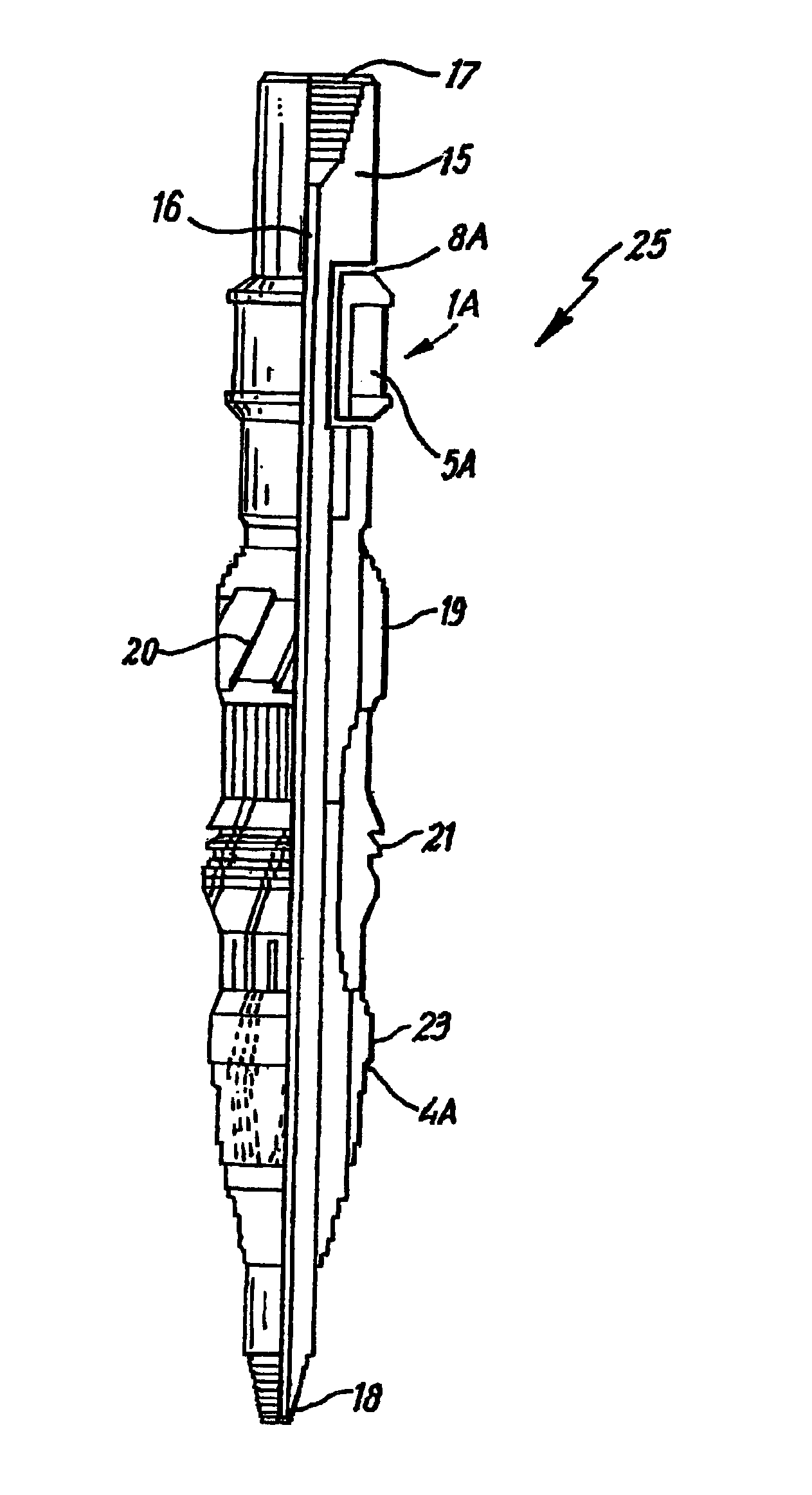
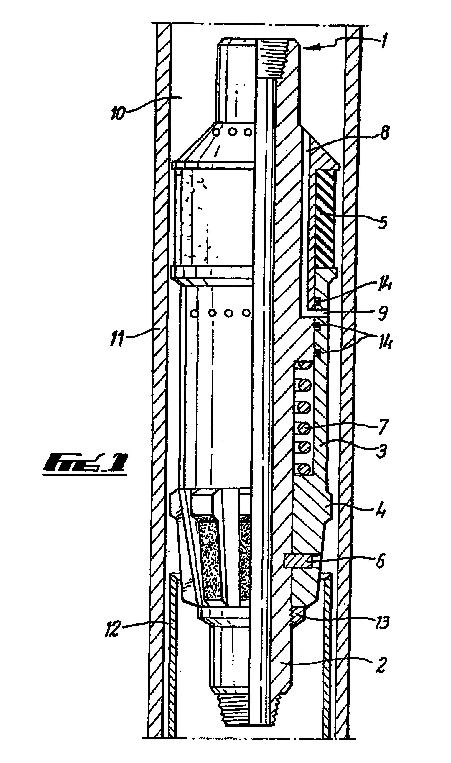
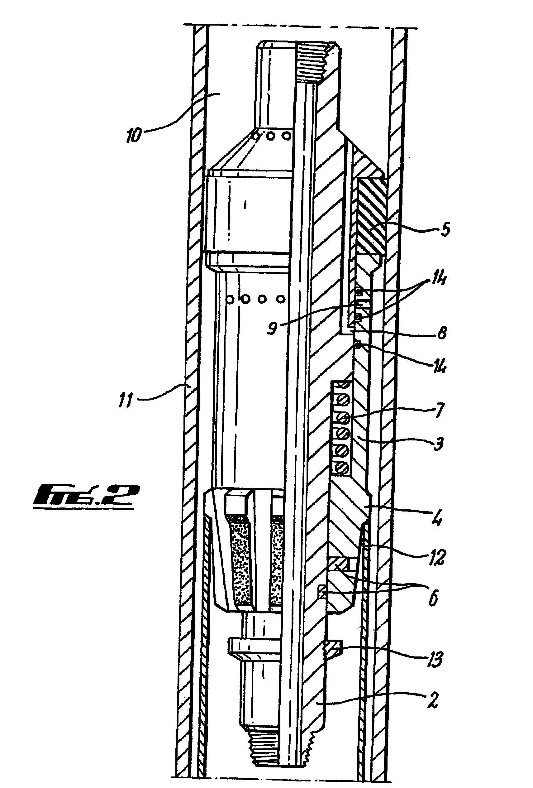
[0035]Referring firstly to FIG. 1 a packer tool is generally depicted at 1 and is comprised of a body 2 and an outer sleeve 3 which is movable in relation to the body 2. The body 2 is mounted on a work string (not shown), typically a drill pipe. The outer sleeve 3 has or is associated with a shoulder 4 which may be a liner top mill. The sleeve 3 is positioned substantially below one or more packer elements 5. The one or more packer elements 5 are typically made from a moulded rubber material. The outer sleeve 3 also has a retainer ring 13.

[0036]The outer sleeve 3 is mechanically attached to the body 2 of the tool 1 by one or more sheer pins 6 and is biased by a spring 7. The body 2 of the tool 1 has an integral bypass channel 8 through which fluid can bypass the area around the packer elements 5, by flowing through the body 2 of the tool 1. The fluid then flows through a bypass port 9 in the sleeve 3. The integral bypass ports 9 and channel 8 are open when the tool is being advanced...


PUM


Abstract

A downhole packer for providing a seal in a well bore to allow integrity testing of the well bore. The packer is set by a sleeve movable on a body of the packer being set down on a formation in the well bore. Movement of the sleeve compresses one or more packing elements. The packer further includes a by-pass channel which allows fluid to pass through the tool as it is run in the well bore, and brushes or scrapers for cleaning the well bore and preparing the location for the packer elements to be contacted upon.

Description

BACKGROUND OF THE INVENTION[0001]The present invention relates to a downhole packer. More particularly, the present invention relates to a packer which can be used for downhole testing.[0002]It is important to determine whether there are any cracks, gaps or other irregularities in the lining of a well bore, or in the cement between tubulars which line a well bore, which may allow the ingress of well bore fluid into the annulus of the bore. It is also important that any irregularities in the well bore casing connections and cement bonds are identified and monitored to prevent contamination of the well bore contents.[0003]It is normally difficult to determine whether there are any irregularities in the well bore casing connections and cement bonds as the hydrostatic pressure created by drilling fluid within the well bore prevents well bore fluid from entering the annulus of the bore. In order to overcome this difficulty it is known to the art to use downhole packers to seal off sectio...

Claims


Application Information

Patent Timeline
Patent Type & Authority Patents(United States)
IPC IPC(8): E21B33/12E21B33/128E21B47/00E21B47/10
CPCE21B47/1025E21B33/128E21B47/117
Inventor HOWLETT, PAUL DAVIDTELFER, GEORGE
Owner SPECIALISED GASOLINEEUM SERVICES GROUP
Why Eureka
Try Eureka