Disk cartridge

Inactive Publication Date: 2005-05-31
SONY CORP
View PDF13 Cites 4 Cited by
  • Summary
  • Abstract
  • Description
  • Claims
  • Application Information

AI Technical Summary

Benefits of technology

[0012]In view of the above problems encountered with the conventional disk cartridge, it is an object of the present invention to provide a disk cartridge in which the above problems can be solved and in which a middle shell is made rotatable and a pair of shutter members are opened and closed based on

Problems solved by technology

When a recording surface of an optical disk or a magnetooptical disk is smudged by dusts, the read or write beam is shielded, also when the information recording surface of the optical disk is damaged by scratches, information cannot be read or written normally.
Therefore, the shutter member having the above U-like shape cannot prevent the disk cartridge from being smudged by very small dusts particles.
In this case, when the information recording surface of the magnetooptical disk 4 is smudged by very small dusts p

Method used


Image

  • Disk cartridge
  • Disk cartridge
  • Disk cartridge

Examples


first embodiment

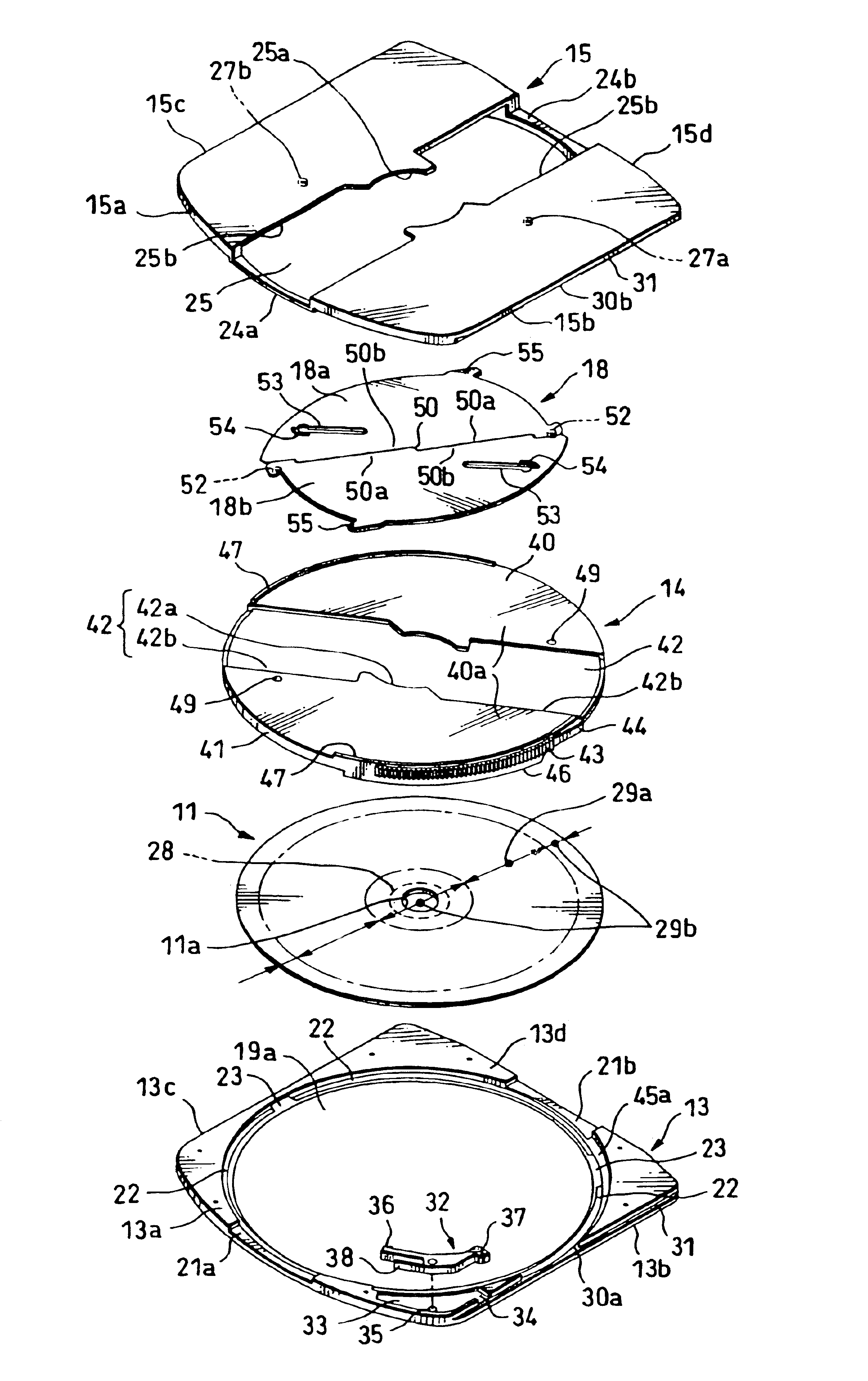
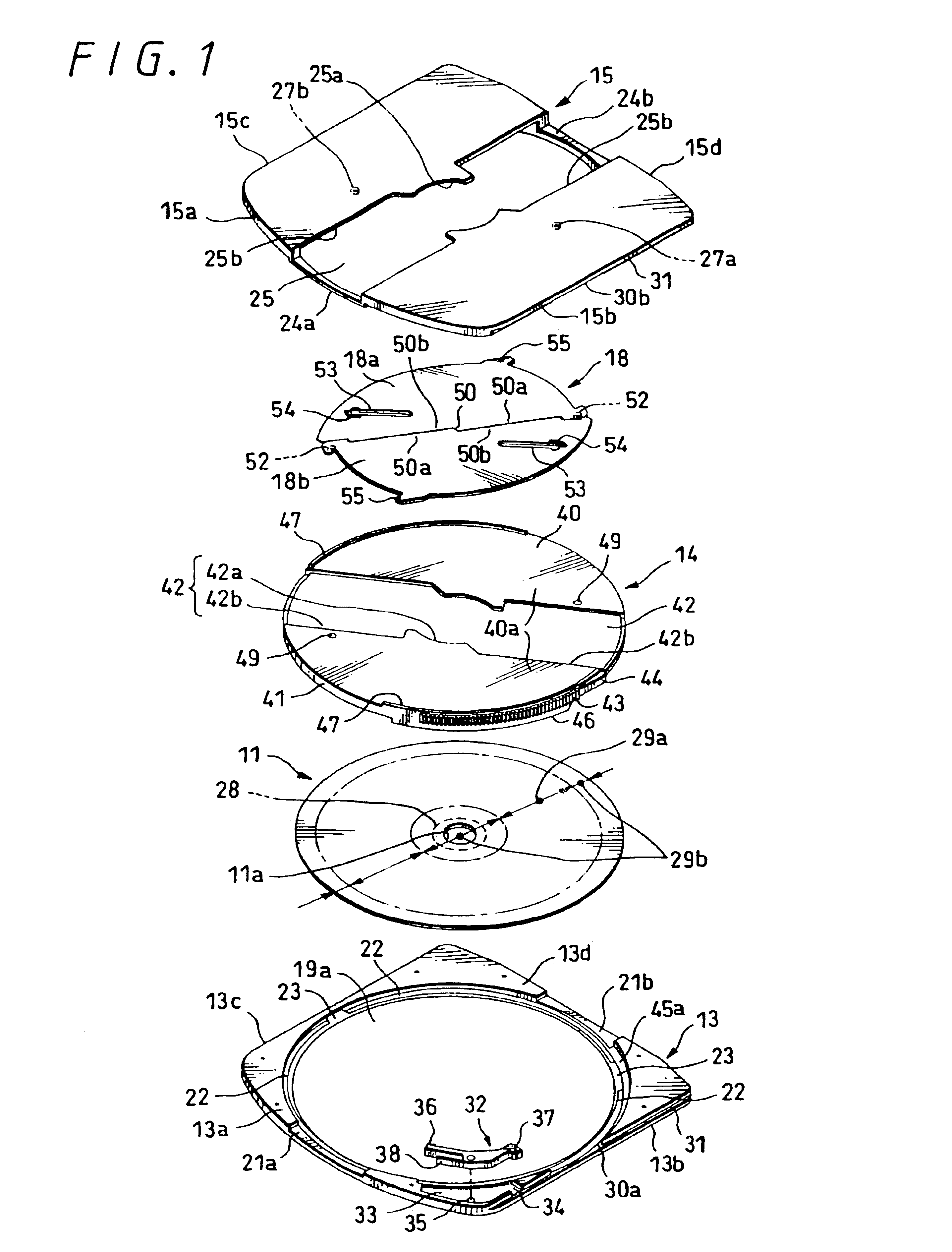
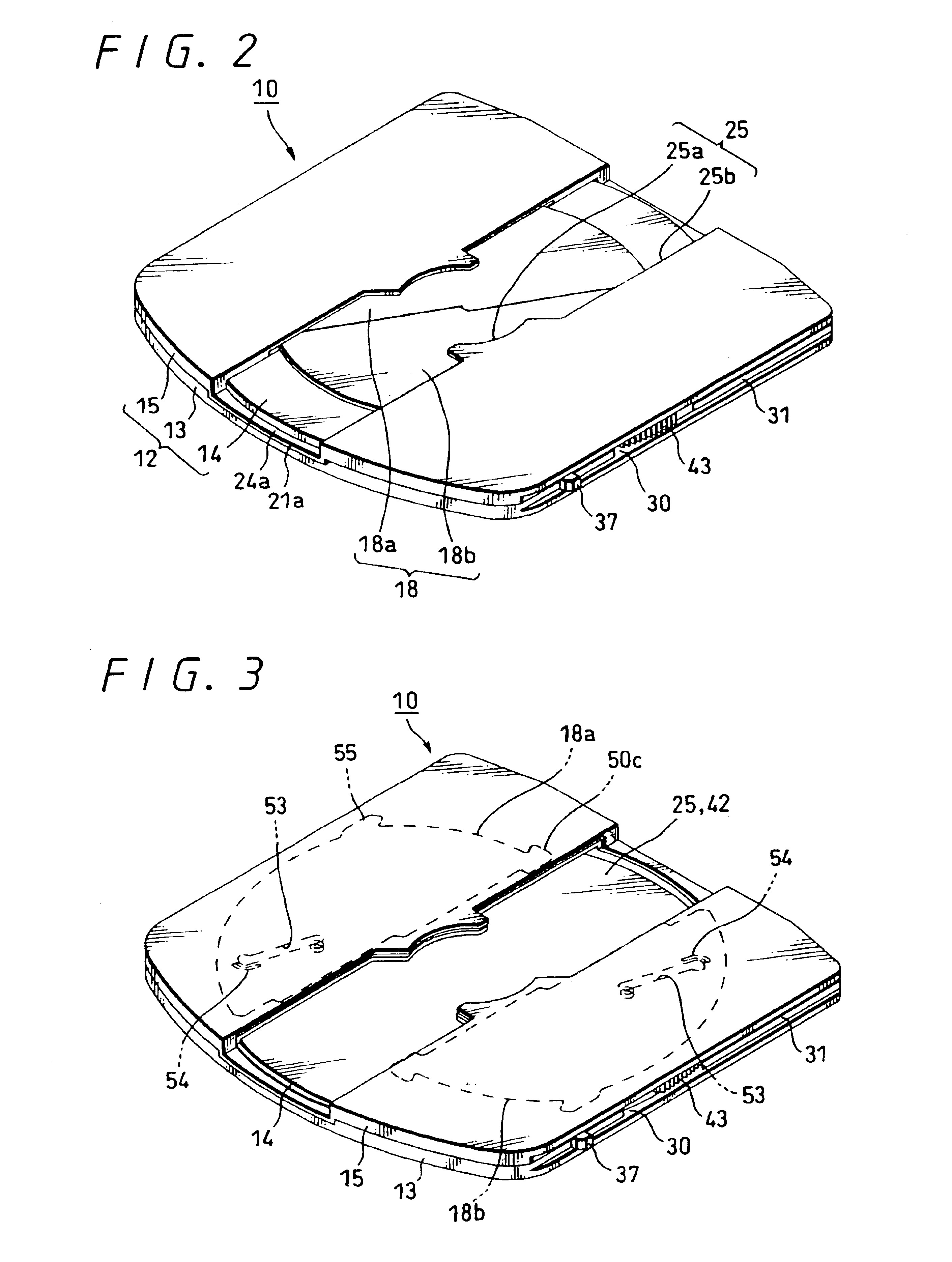
[0066]Embodiments of the present invention will be described below with reference to the accompanying drawings. FIG. 1 to 26 are diagrams showing disk cartridges according to the embodiments of the present invention. Specifically, FIG. 1 is an exploded perspective view showing a disk cartridge from a lower shell side. FIG. 2 is a perspective view showing the same disk cartridge with its shutter being closed from the lower shell side. FIG. 3 is a perspective view showing the same disk cartridge with its shutter being opened. FIG. 4 is a bottom view of an upper shell. FIG. 5 is bottom view of a middle shell. FIG. 6 is a plan view of the lower shell. FIG. 7 is a perspective view showing the middle shell and a pair of shutter members being opened. FIG. 8 is a perspective view showing the state in which the pair of shutter members shown in FIG. 7 are being opened. FIG. 9 is a perspective view showing the lower shell and the pair of shutter members being opened. FIG. 10 is a perspective ...

second embodiment

[0067]FIGS. 13 to 19 are explanatory diagrams showing a relationship between the rotation amount of the middle shell and the opened and closed states of the pair of shutter members, respectively. FIGS. 20A to 20C are explanatory diagrams showing a relationship between the rotation of the middle shell and the ascending and descending operations, respectively. FIGS. 21A and 21B are explanatory diagrams showing the state in which the shutter members are closely contacted / released based on the ascending and descending operations executed when the middle shell is rotated. FIG. 22 is an exploded perspective view showing a disk cartridge from a lower shell side. FIG. 23 is a perspective view showing the same disk cartridge from the lower shell side with the shutter closed. FIG. 24 is a block diagram to which reference will be made in explaining a circuit arrangement of an information disk recording and reproducing apparatus which can use the inventive disk cartridge according to an embodi...


PUM


Abstract

A disk cartridge in which a pair of shutter members can be opened and closed smoothly and reliably, and a dust-proof property and an airtightness of a large opening portion can be increased by reducing a space between a pair of shutter members and a cartridge housing as much as possible. The disk cartridge comprises a cartridge housing in which a disk compartment is formed-between an upper shell and a middle shell by overlapping the upper shell, the middle shell and the lower shell and the middle shell is supported by the upper shell and the lower shell so as to become freely rotatable, an optical disk rotatably stored within the disk compartment and a pair of shutter members attached to the middle shell in such a manner that they can be moved in the plane direction on the same plane. A shutter opening and closing mechanism for opening and closing opening portions by moving the pair of shutter members based rotation of the middle shell.

Description

CROSS-REFERENCE TO RELATED APPLICATIONS[0001]This application is a continuation application of U.S. patent application Ser. No. 09 / 858,759, filed May 16, 2001, now U.S. Pat. No. 6,700,741.BACKGROUND OF THE INVENTION[0002]1. Field of the Invention[0003]The present invention relates to a disk cartridge having a cartridge housing in which a disk-like recording medium such as an optical disk, a magnetooptical disk and a magnetic disk is stored in a disk compartment so as to become freely rotatable, and particularly to a disk cartridge in which a pair of shutter members are opened and closed to open and close an opening portion by rotating a middle shell which forms a disk compartment between it and an upper shell or a lower shell and a part of a disk-like recording medium is exposed from the opening portion when the opening portion is opened.[0004]2. Description of the Related Art[0005]As a disk cartridge in which a disk-like recording medium in and / or from which audio information, vide...

Claims


Application Information

Patent Timeline
IPC IPC(8): G11B23/03
CPCG11B23/0316G11B23/0308G11B17/0436G11B23/0315G11B2220/2537G11B2220/2525G11B2220/2508
Inventor INOUE, NAOKIOBATA, MANABU
Owner SONY CORP
Why Eureka
Try Eureka