Tire pressure indicator

a technology of tire pressure and indicator, which is applied in the direction of tire measurement, vehicle components, transportation and packaging, etc., can solve the problems of tire failure, increase the life of tires, tire failure, etc., and achieve the effect of reducing the pressure below the diaphragm and increasing the air pressur

Inactive Publication Date: 2005-06-28
TAGG TECH CORP
View PDF27 Cites 37 Cited by
  • Summary
  • Abstract
  • Description
  • Claims
  • Application Information

AI Technical Summary

Problems solved by technology

First, it is noted that under inflation of vehicular tires is the leading cause of tire failure.
Second, the maintenance of proper tire inflation promotes more even tread wear and thus increases the life of the tire.
Tire failure is generally caused by overheating which is typically caused by under inflation of the tire and / or by overloading of the vehicle.
More specifically, tire heating is caused by the normal flexure of the tire sidewalls and road friction.
However, if the tires are under inflated, greater sidewall flexure along with tire heating results.
Thus, in the circumstance in which tires are under inflated, overheating and tire failure are more likely to occur.
Mechanical tire pressure gauges of the above-described type typically require a great deal of user intervention or do not provide a constant and instantaneous indication of whether the tire is under inflated.
Tire pressure is often not measured due to the inconvenience associated with the use of typical mechanical tire pressure gauges and consequently drivers are often operating their vehicles on under inflated tires.

Method used


Image

  • Tire pressure indicator
  • Tire pressure indicator
  • Tire pressure indicator

Examples


Embodiment Construction

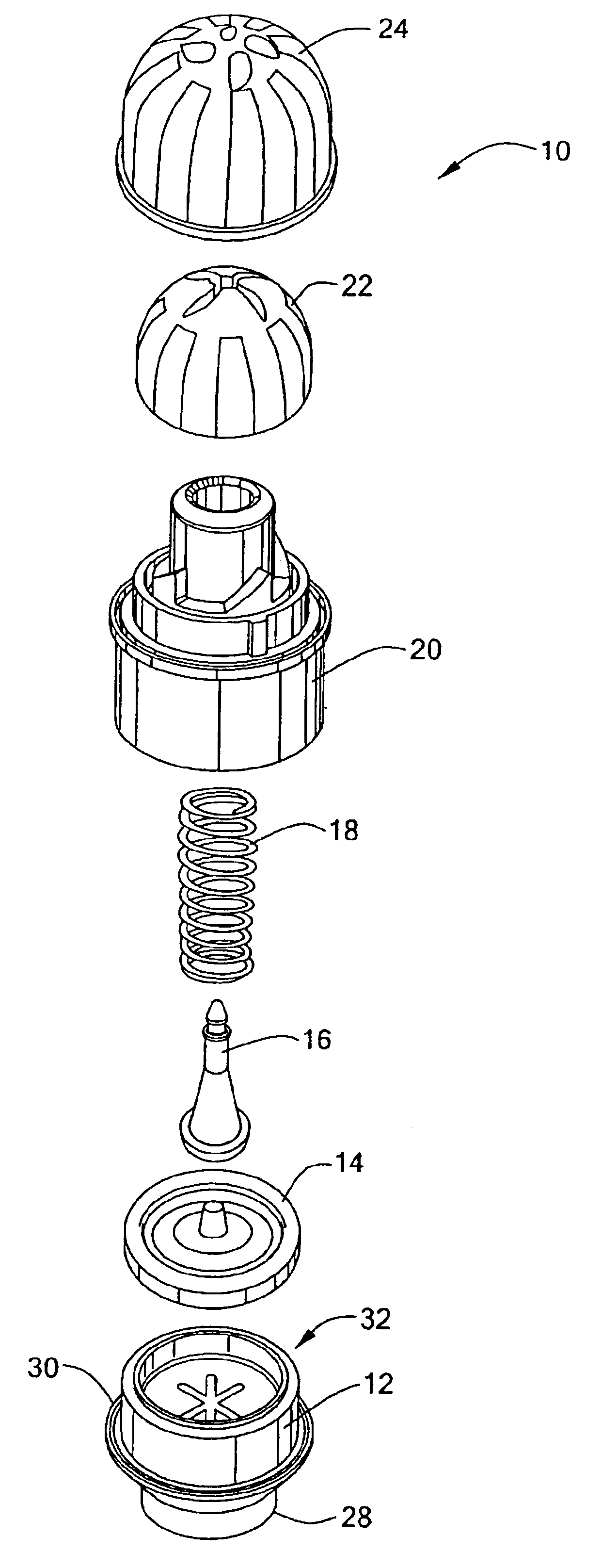
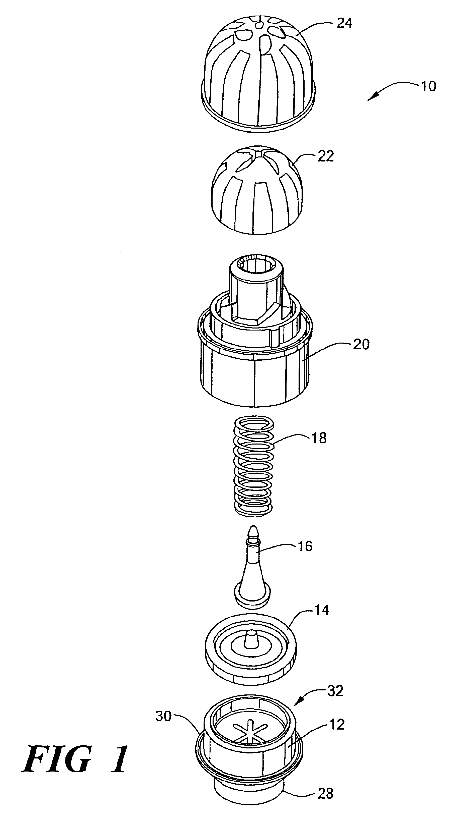
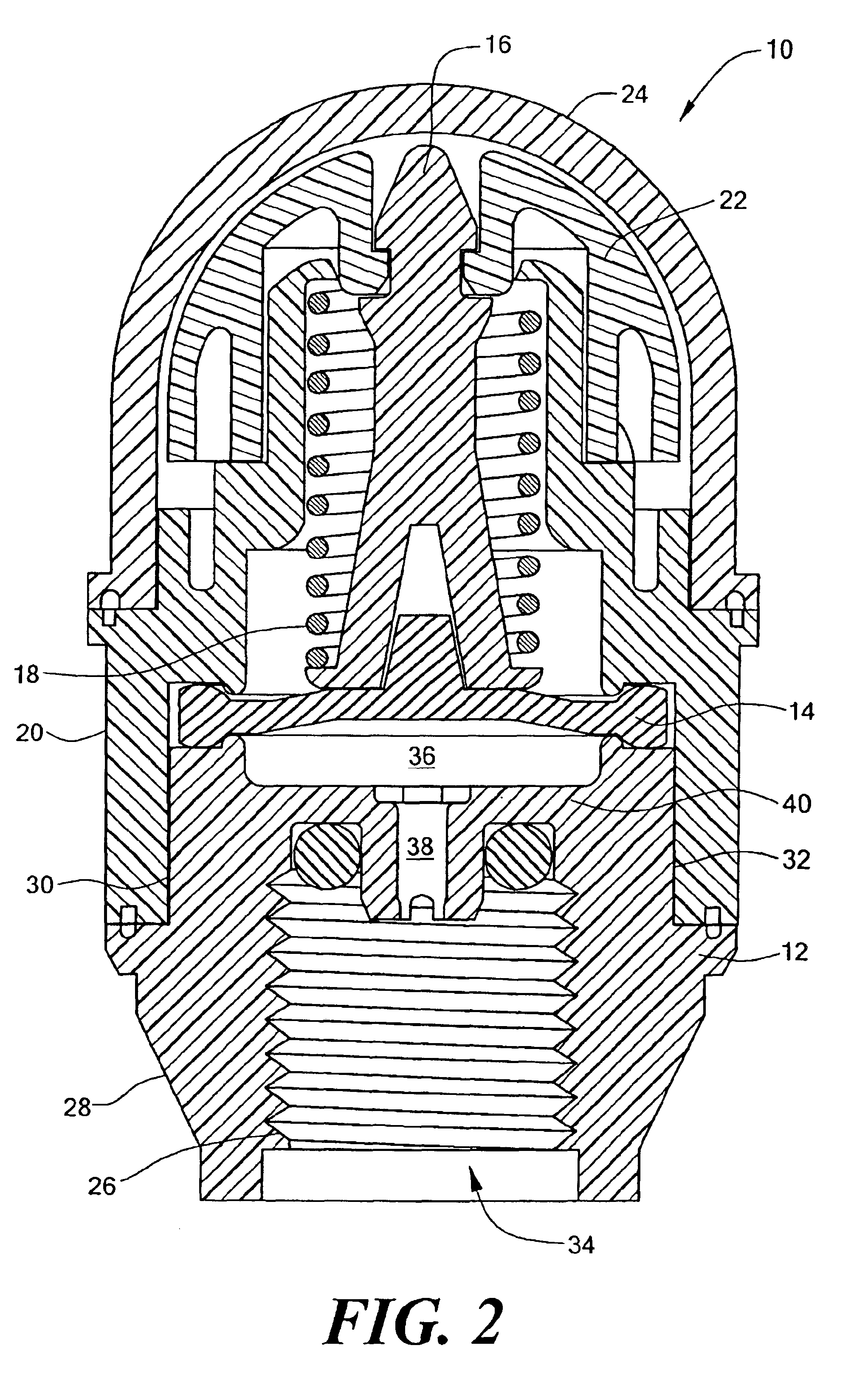
[0033]In accordance with the present invention, a tire pressure indicator is disclosed. The tire pressure indicator is coupled to the valve stem of a tire and provides a visual indication of whether the tire pressure is above or below a predetermined pressure limit. A determination may thus be made by visual inspection of the indicator as to whether the tire pressure is below a tire pressure value recommended for safe operation of the vehicle. Referring to FIGS. 1-8, the tire pressure indicator 10 includes a base 12, a diaphragm 14, a post 16, a spring 18, a collar 20, an indicator 22 and a cover 24. The tire pressure indicator includes first and second camming mechanisms that define first and second rotational orientations of the indicator with respect to the cover as subsequently described. The first camming mechanism is operative during axial movement of the indicator in a first direction when the air pressure is above a specified pressure limit to cause rotation of the indicator...


PUM


Abstract

A tire pressure indicator for coupling with a valve stem of a tire. The tire pressure indicator provides a first visual indication in the event that the tire pressure is below a first threshold limit and a second visual indication if the tire pressure is above a second threshold limit. The pressure indicator includes a dome shaped indicator and a dome shaped cover that is mounted over the indicator. The cover includes a plurality wedge shaped transparent viewing windows extending from near the top of the dome. The transparent viewing windows are separated by opaque portions. The indicator has a plurality of alternating wedge shaped areas of first and second colors extending from near the top of the dome to the lower peripheral edge of the indicator. The rotation of the indicator is related to the tire pressure. In one orientation of the indicator that occurs when the tire pressure is below a first predetermined limit, the first color is visible through the transparent viewing windows of the outer dome. In a second orientation of the inner dome that exists when the tire pressure is above a second predetermined limit, the second color is visible through the viewing windows of the outer dome.

Description

CROSS REFERENCE TO RELATED APPLICATIONS[0001]Not ApplicableSTATEMENT REGARDING FEDERALLY SPONSORED RESEARCH OR DEVELOPMENT[0002]Not ApplicableBACKGROUND OF THE INVENTION[0003]This invention is directed to a tire pressure indicator that can readily be installed on valve stems of vehicle tires to provide a highly visible indication when the tire pressure is above or below a predetermined limit.[0004]Proper maintenance of tire pressure is important in the operation of a motor vehicle for a number of reasons. First, it is noted that under inflation of vehicular tires is the leading cause of tire failure. Second, the maintenance of proper tire inflation promotes more even tread wear and thus increases the life of the tire. Lastly, a vehicle with properly inflated tires will exhibit greater gas mileage than a vehicle with under inflated tires.[0005]Tire failure is generally caused by overheating which is typically caused by under inflation of the tire and / or by overloading of the vehicle....

Claims


Application Information

Patent Timeline
Patent Type & Authority Patents(United States)
IPC IPC(8): B60C23/00
CPCB60C23/0496
Inventor GLADSTONE, PETERMORRIS, JASON A.TINSTMAN, MICHAEL D.AYLOUCHE, MARWAN M.HOLLAND, ROBERT S.
Owner TAGG TECH CORP
Why Eureka
Try Eureka