Force detection device

a detection device and force technology, applied in the direction of stringed rackets, instruments, apparatus for force/torque/work measurement, etc., can solve the problem of a complex three-dimensional problem

Active Publication Date: 2005-07-12
WAKO CO LTD
View PDF56 Cites 88 Cited by
  • Summary
  • Abstract
  • Description
  • Claims
  • Application Information

AI Technical Summary

Benefits of technology

[0005]Thus an object of this invention is to provide a force detection device that can detect forces and moments in a distinguished manner by means of a structure that is as simple as possible.

Problems solved by technology

However priorly, regardless of the displacement detection type or the strain detection type, a force detection device of a considerably complex three-dimensional structure was required to detect the respective components independent of each other.

Method used


Image

  • Force detection device
  • Force detection device
  • Force detection device

Examples


first embodiment

>>

[0316]The major structural parts of a force detection device of a first embodiment of this invention shall now be described using FIGS. 9 to 12 and furthermore, the operation principle of this device shall be described using FIGS. 13 to 15.

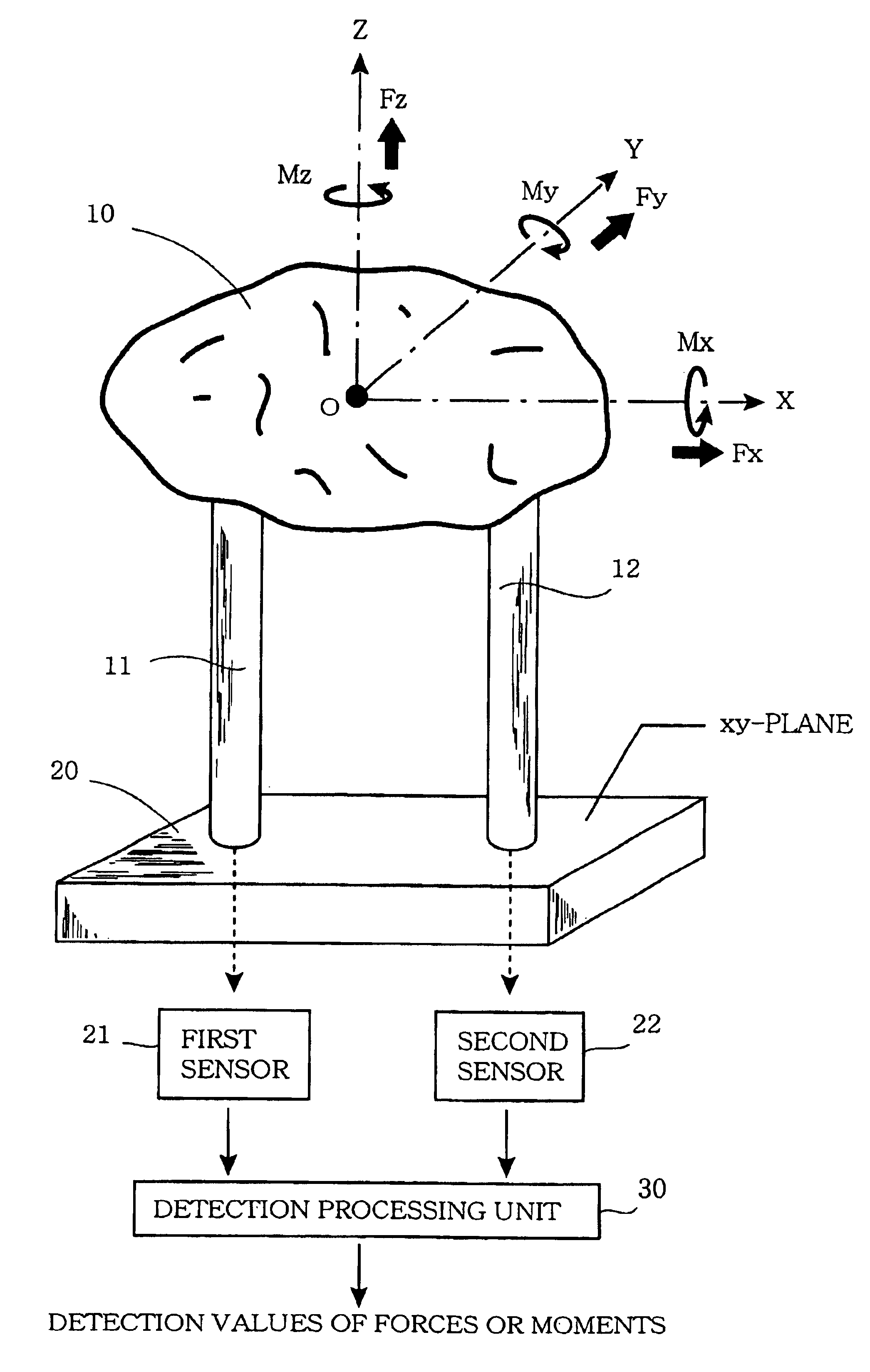
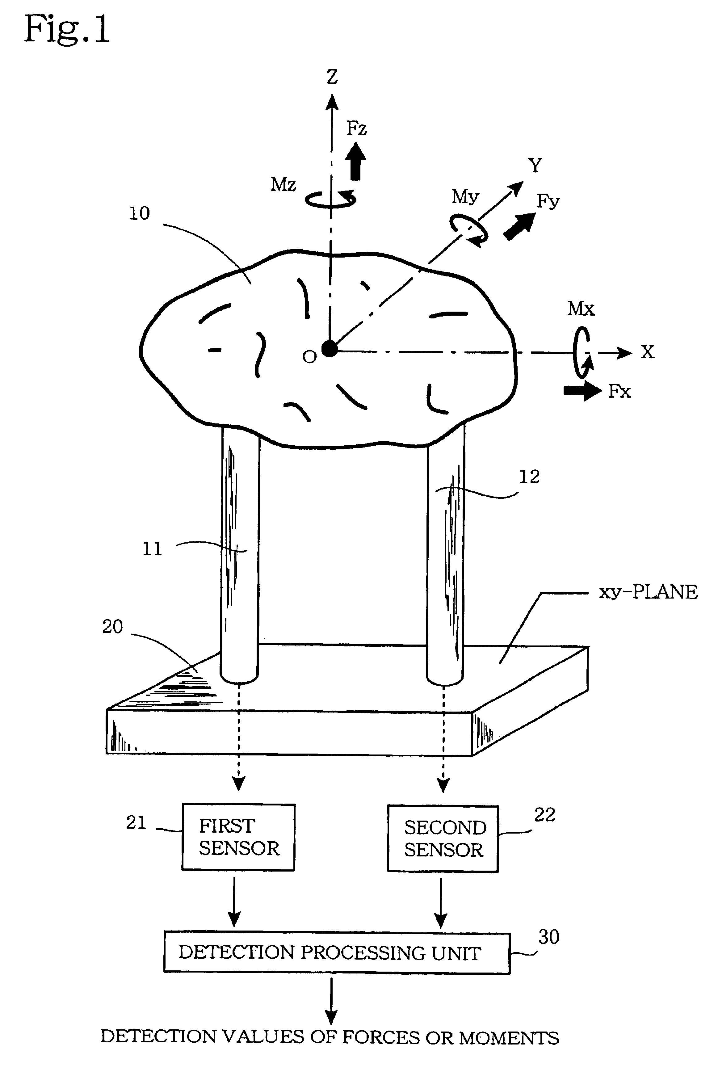
[0317]FIG. 9 is a side view in section across the XZ plane showing the major structural parts of the force detection device of this first embodiment, and FIG. 10 is a top view of this device. As shown in FIG. 9, the basic components of this force detection device are a force receiving member 100, an intermediate member 200, and a supporting member 300, and the basic form of each of these is a plate-like member having a top surface of square shape.

[0318]As shown in FIG. 10, force receiving member 100 is basically a plate-like member having a top surface with a square shape and having two cylindrical protruding parts 110 and 120 extending downwards from the bottom surface. FIG. 11 is a transverse section along the XY plane of force receiving membe...

second embodiment

>>

[0350]A force detection device of a second embodiment of this invention shall now be described. FIG. 16 is a top view of the major structural parts of the force detection device of this second embodiment, and FIG. 17 is a side view in section along line 17-17 of the force detection device shown in FIG. 16. The section along line 9-9 of the force detection device shown in FIG. 16 is the same as FIG. 9. A difference with respect to the above-described force detection device of the first embodiment is that four columnar force transmitting members are provided, and besides this, the structure and materials are exactly the same as those of the force detection device of the first embodiment. That is, the overall device is arranged as a structure comprising a plate-like force receiving member 100, an intermediate member 200, and a supporting member 300, each having a top surface with a square shape.

[0351]As shown in the top view of FIG. 16, force receiving member 100 is basically a plate...

third embodiment

>>

[0371]A force detection device of a third embodiment of this invention shall now be described. Like the above-described force detection device of the second embodiment, the force detection device of the third embodiment performs detection using four columnar force transmitting members and four sensors S1 to S4. However, the present embodiment differs slightly in the positioning of the four columnar force transmitting members. A description shall now be provided concerning just this difference.

[0372]FIG. 21 is a top view of a supporting member 300 used in the force detection device of the third embodiment. A comparison with FIG. 18, which is a top view of supporting member 300 used in the above-described force detection device of the second embodiment, clearly shows the differences between the two. That is, as shown in FIG. 18, with the second embodiment, fixed electrodes E11 to E15, E21 to E25, E31 to E35, and E41 to E45, which are components of the four sensors S1 to S4, are resp...


PUM

PropertyMeasurementUnit
forceaaaaaaaaaa
flexibilityaaaaaaaaaa
force transmittingaaaaaaaaaa

Abstract

Forces and moments are detected in a distinguishing manner by a simple structure. A supporting member (20) is positioned below a force receiving member (10), which receives forces to be detected, and between these components, at least two columnar force transmitting members (11, 12) are connected. Connecting members having flexibility are interposed at the upper and lower ends of each of columnar force transmitting members (11, 12) so that columnar force transmitting members (11, 12) can become inclined when force receiving member (10) becomes displaced upon receiving a force. Sensors (21, 22) are positioned at the respective connection parts of columnar force transmitting members (11, 12) and supporting member (20) to detect forces that are transmitted from the respective columnar force transmitting members (11, 12) to supporting member (20). Based on the detection values of sensors (21, 22), detection processing unit 30 detects, in a distinguishing manner, forces and moments acting on force receiving member (10). When four columnar force transmitting members are used, all of forces Fx, Fy, and Fz and moments Mx, My, and Mz can be detected.

Description

BACKGROUND OF THE INVENTION[0001]This invention concerns a force detection device, and particularly concerns a force detection device suited for measuring forces and moments independently.[0002]Various types of force detection devices are used for controlling motions of robots and industrial machines. Compact force detection devices are also incorporated as man-machine interfaces of input devices for electronic equipment. In order to achieve size and cost reduction, a force detection device used in such an application is required to be as simple in structure as possible and is required to detect forces of the respective coordinate axes in three-dimensional space independently each other.[0003]Multi-axis force detection devices that are presently used can be classified into two types, that is, a type, with which specific directional components of a force that acts on a three-dimensional structure are detected as displacements that arise at a specific part, and a type, with which the ...

Claims


Application Information

Patent Timeline
Patent Type & Authority Patents(United States)
IPC IPC(8): G01L5/16G01L1/14
CPCG01L5/165
Inventor OKADA, KAZUHIRO
Owner WAKO CO LTD
Why Eureka
Try Eureka