Portable membrane packing apparatus

a technology of packing apparatus and membrane, which is applied in the directions of transportation and packaging, paper hanging, bundling articles, etc., can solve the problems of inconvenient us

Inactive Publication Date: 2005-07-26
VAN GLABBEEK RENE
View PDF11 Cites 41 Cited by
  • Summary
  • Abstract
  • Description
  • Claims
  • Application Information

AI Technical Summary

Problems solved by technology

In former times, membrane packing work used to be done manually without help of any accessory, that is, a user had to hold a membrane reel with one hand and draw the membrane out of the membrane reel and carry out packing with the other hand, quite inconvenient in use.

Method used


Image

  • Portable membrane packing apparatus
  • Portable membrane packing apparatus
  • Portable membrane packing apparatus

Examples


Embodiment Construction

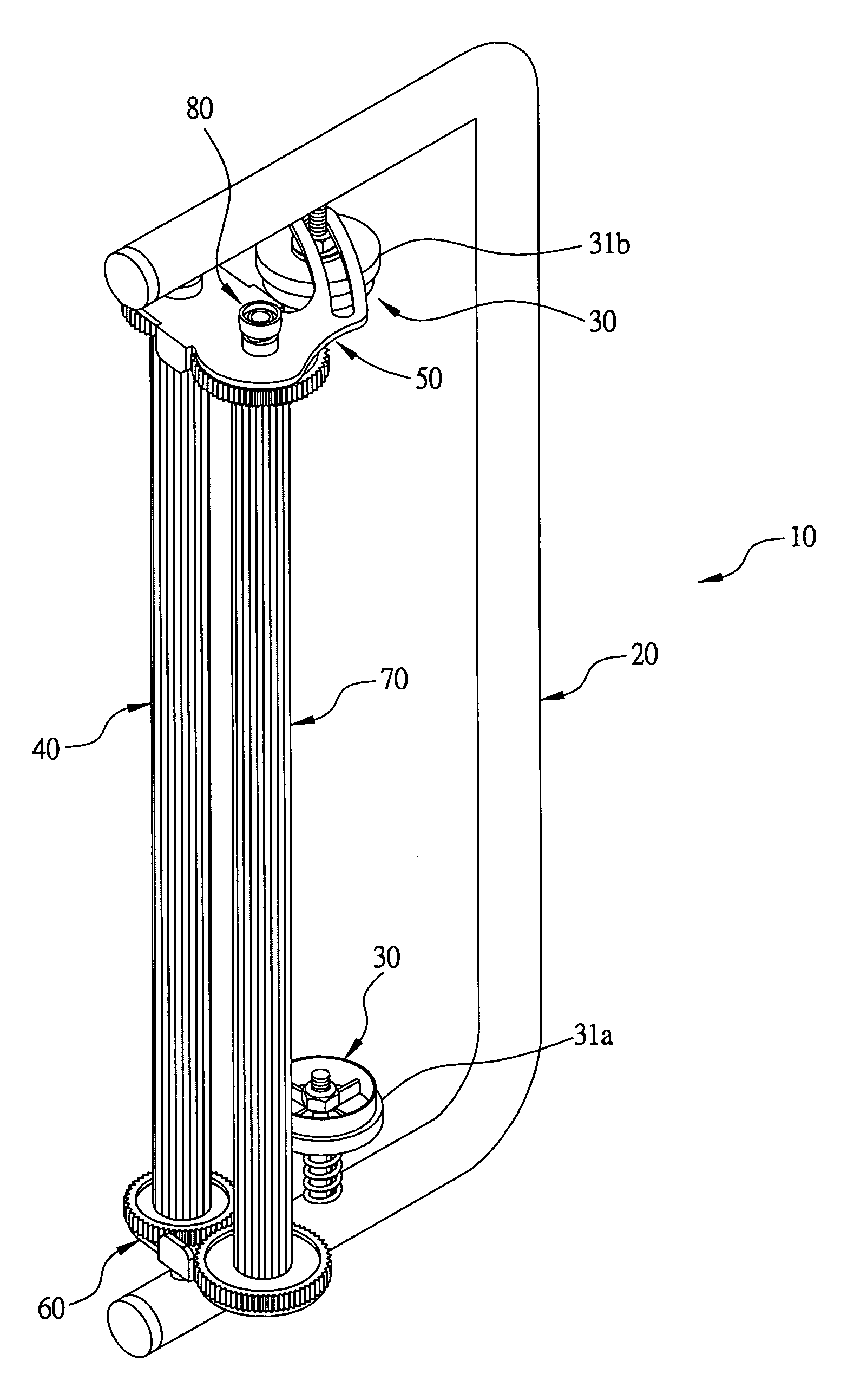
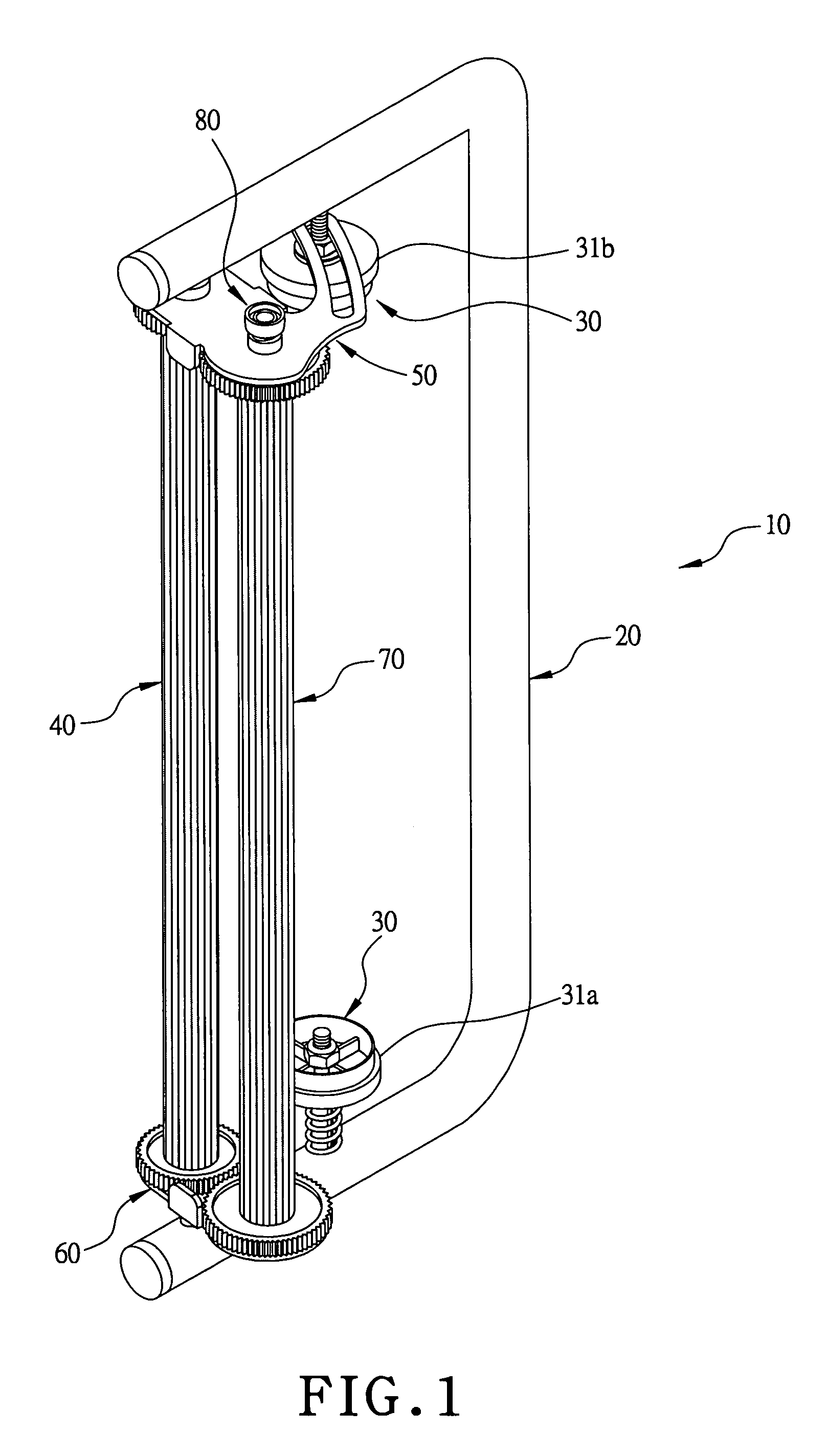
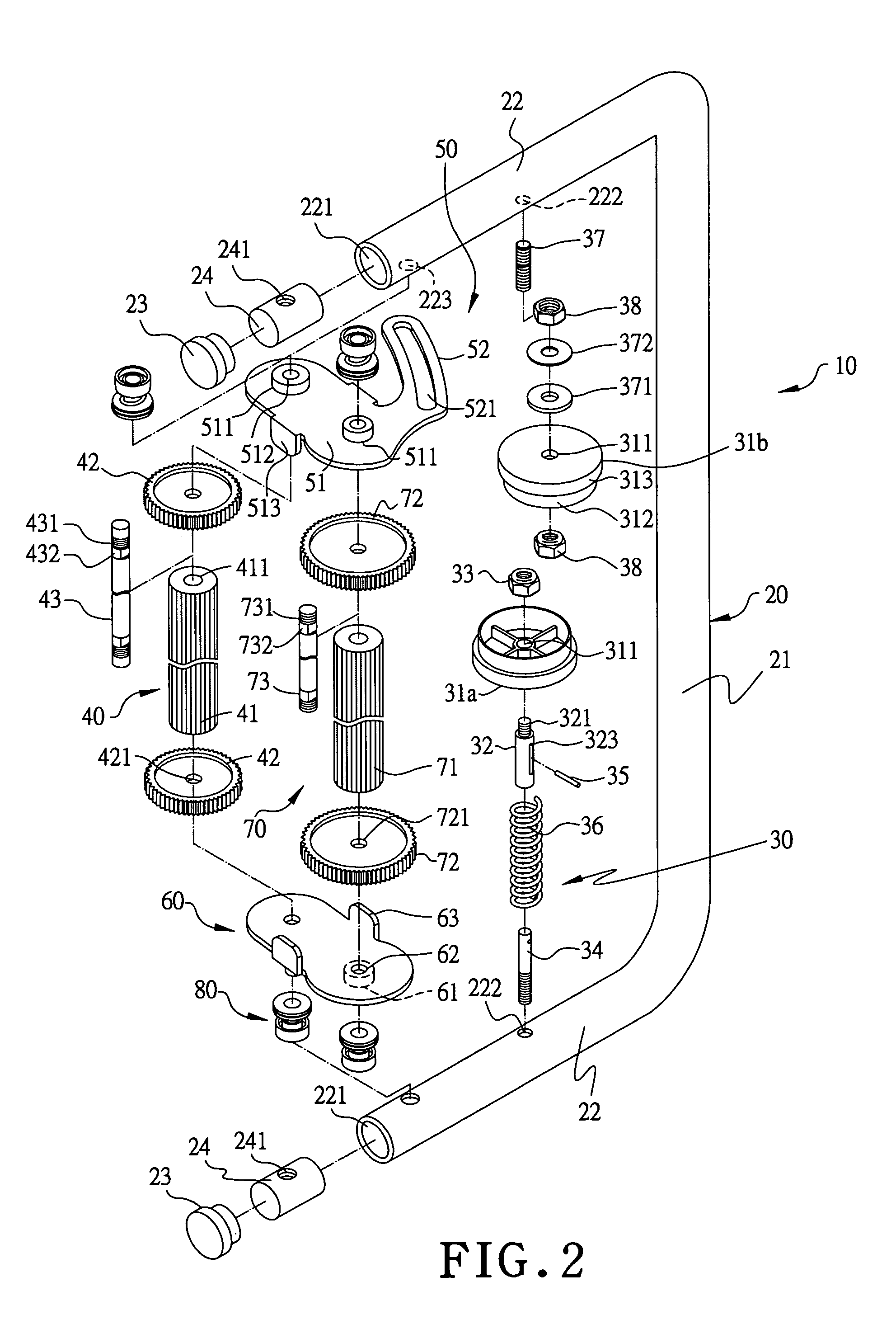
[0016]A preferred embodiment of a portable membrane packing apparatus in the present invention, as shown in FIGS. 1 and 2, includes a holding-and-drawing rod 20, two reel connecting units 30, a first roller unit 40, a swaying plate 50, a connecting plate 60, a second roller unit 70 and four elastic compression units 80 combined together.

[0017]The holding-and-drawing rod 20 is an elongate round tube having its intermediate portion formed with lengthwise holding rod 21 and its opposite ends respectively bent inward to form a transverse combining rod 22 having a tube end hole 221 to be clogged by an end plug 23. Each combining rod 22 is bored with an insert hole 222 in the inner wall of an intermediate portion and a shaft hole 223 in the inner wall of a portion near the end. The two combining rods 22 have their tube end holes 221 respectively clogged with a column-shaped positioning block 24 having a threaded hole 241 in the circumferential wall and able to be turned around to let its ...


PUM

PropertyMeasurementUnit
distanceaaaaaaaaaa
elastic compressionaaaaaaaaaa
diameteraaaaaaaaaa

Abstract

A portable membrane packing apparatus includes a holding-and-drawing rod, two reel connecting units, a first roller unit, a swaying plate, a connecting plate, a second roller unit, and four elastic compressing units. The first roller unit is axially assembled at the ends of the opposite combing rods, and the swaying plate and the connecting plate are respectively provided between the first roller unit and the combining rods, with the swaying plate restricted to sway biasly.

Description

BACKGROUND OF THE INVENTION[0001]1. Field of the Invention[0002]This invention relates to a portable membrane packing apparatus, particularly to one able to quickly carry out packing on a loading plank and the articles piled thereon with membrane with one hand.[0003]2. Description of the Prior Art[0004]Generally, loading planks are extensively employed in factories, warehouses or freight handling centers for articles or commodities to be orderly placed or piled up thereon so as to prevent the them from contacting with the ground and being wetted. When these articles or commodities are to be moved to other locations, a lift truck can be used to prop up the loading plank together with the articles or the commodities piled thereon and move them to a given location.[0005]To prevent the peripheral sides of the articles piled on the loading plank from being soiled and wetted during the process of depositing or to prevent the articles or commodities from swaying or falling in the process o...

Claims


Application Information

Patent Timeline
Patent Type & Authority Patents(United States)
IPC IPC(8): B65B67/08B65B67/00
CPCB65B67/085Y10T156/1788Y10T156/18Y10T156/1795
Inventor YU CHEN, HSIU-MAN
Owner VAN GLABBEEK RENE
Why Eureka
Try Eureka