Projection television cabinet having a one-piece reference structure

a reference structure and projection television technology, applied in the field of projection television systems, can solve the problems of increasing geometric distortion and requiring an increased range of adjustment of optical components

Inactive Publication Date: 2005-07-26
THOMSON LICENSING SA
View PDF28 Cites 31 Cited by
  • Summary
  • Abstract
  • Description
  • Claims
  • Application Information

AI Technical Summary

Problems solved by technology

Increased tolerance stack in the location of the critical optical components, undesirably increases geometric distortions of the television images and requires an increased range of adjustment of the optical components to correct these distortions.

Method used


Image

  • Projection television cabinet having a one-piece reference structure
  • Projection television cabinet having a one-piece reference structure
  • Projection television cabinet having a one-piece reference structure

Examples


Embodiment Construction

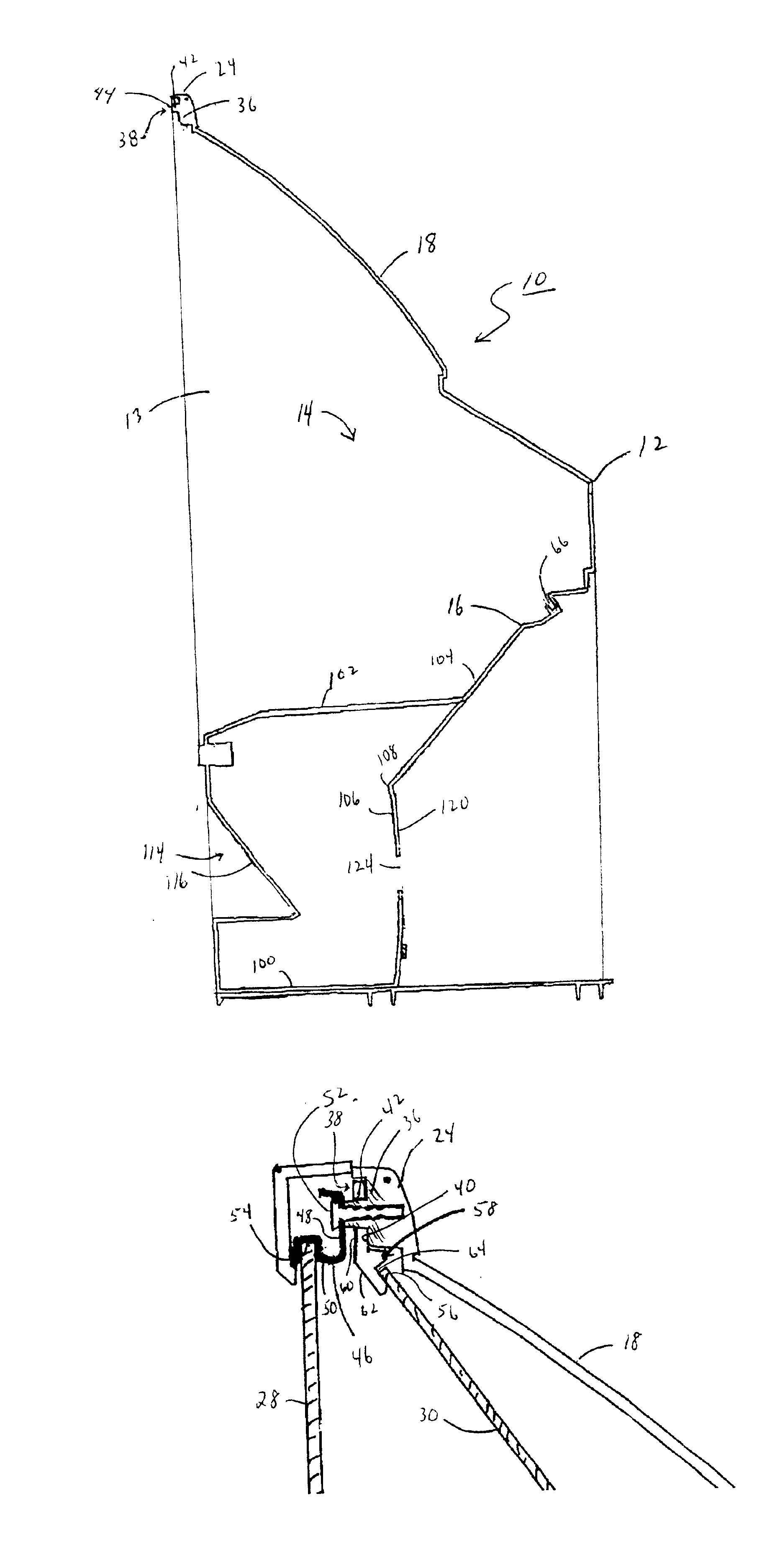
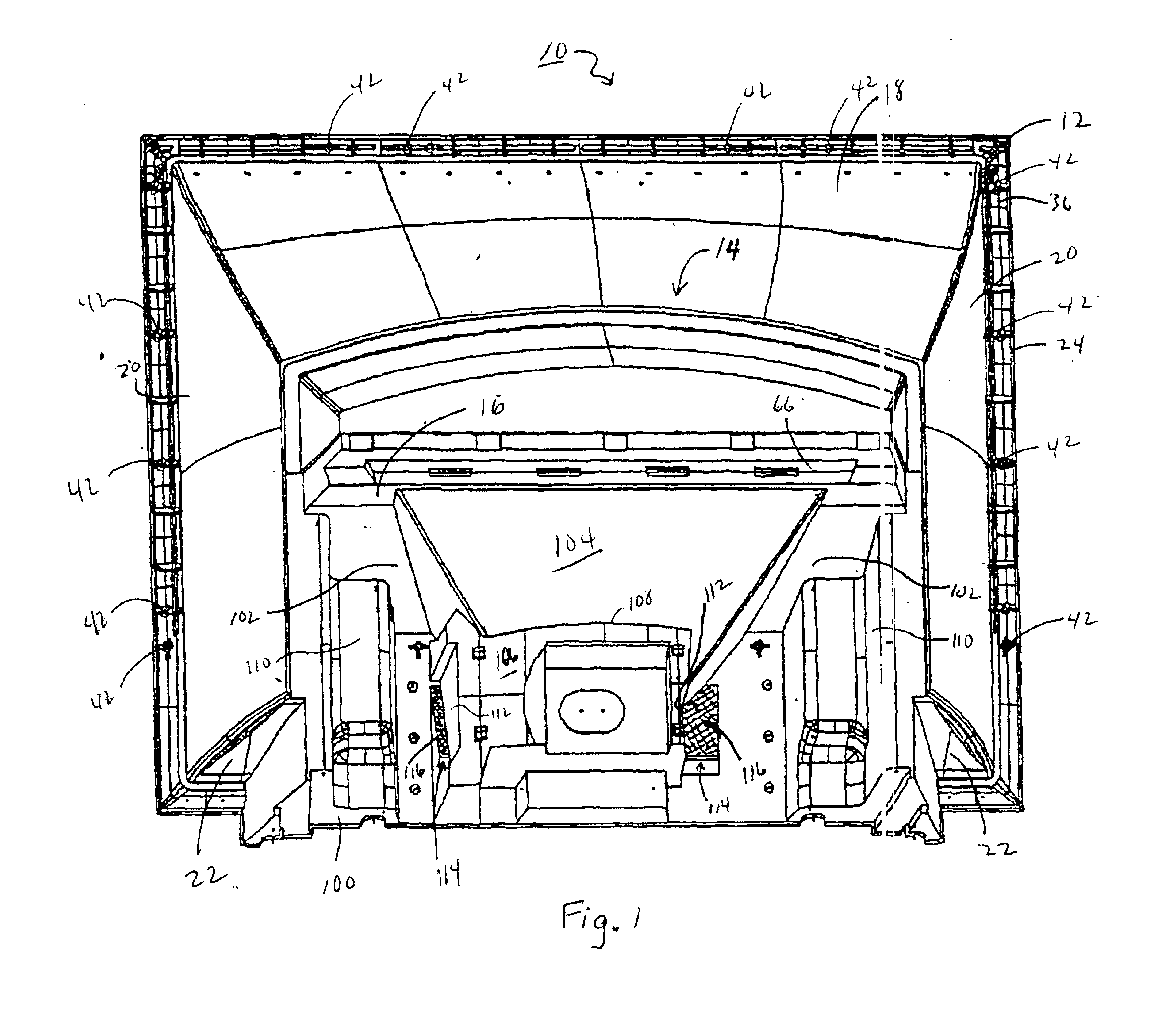
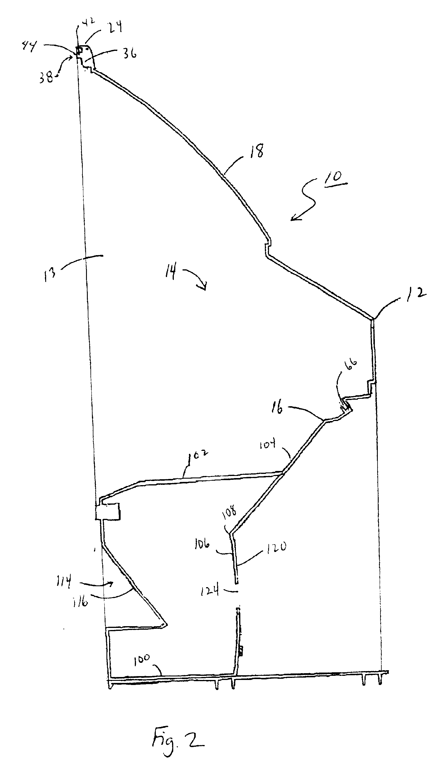
[0018]FIGS. 1 and 2 collectively illustrate a projection TV system cabinet 10 made according to a preferred embodiment of the invention. The cabinet 10 generally comprises a self-supporting, one-piece, open-front enclosure 12 molded from a plastic material. Preferably, the enclosure 12 is made using a conventional gas injection molding process which minimizes internal stresses in the enclosure 12 and thus, dimensionally stabilizes the enclosure 12. The lower portion 14 of the enclosure 12 defines a frame section 16 that provides the enclosure 12 with rigidity. The frame section 16 is covered by an inclined top wall 18 and surrounded by a pair of side walls 20 with bottom edges 22 that turn inwardly toward the lower frame section 16. A flange 24 is molded with front edges of the top and side walls 18, 20.

[0019]As shown in FIGS. 3 and 4, the cabinet 10 of the invention houses all critical optical components commonly used in a projection TV system including a light projector assembly 2...


PUM


Abstract

A cabinet for a projection television system, the cabinet including a one-piece molded structure for mounting the components, and reference surfaces unitary with the structure, for mechanically aligning critical optical components of the television system with one another.

Description

[0001]This application claims the benefit of U.S. Provisional Application No. 60 / 178,330, filed Jan. 27, 2000, entitled “Projection tv cabinet concept with all critical alignment parts mounted to one reference part”.BACKGROUND[0002]The present invention relates to projection television systems, and more particularly, to a molded plastic television cabinet having reference features molded into one part for aligning the critical optical components of the projection television system.[0003]A conventional projection television (TV) system typically consists of a plurality of critical optical components mounted in a multi-part cabinet structure. The optical components commonly include a light projector assembly for generating television images, a screen for viewing the images, and a large mirror (often combined with a smaller mirror) for directing the images generated by the light projector assembly to the screen. The multi-part cabinet structure usually includes a front section having a...

Claims


Application Information

Patent Timeline
Patent Type & Authority Patents(United States)
IPC IPC(8): H04N5/74G03B21/10H04N5/64
CPCH04N9/3141H04N5/74
Inventor DUGGAN, SCOTT JOSEPHRITTER, DARIN BRADLEY
Owner THOMSON LICENSING SA
Why Eureka
Try Eureka