Barbecue grill assembly

a grill and grill assembly technology, applied in the field of barbecue grill assembly, can solve the problems of affecting the versatility of the barbecue grill assembly, the size and configuration of the support frame and the firebox cannot be altered, and the barbecue grill assembly is not suitable for use in domestic stoves or ranges

Inactive Publication Date: 2005-08-09
WEBER-STEPHEN PRODUCTS
View PDF20 Cites 32 Cited by
  • Summary
  • Abstract
  • Description
  • Claims
  • Application Information

AI Technical Summary

Benefits of technology

[0007]The present invention relates to a barbecue grill assembly. More specifically, the present invention relates to a barbecue grill assembly having a cooking chamber and a support frame assembly. The support frame assembly is adapted to provide support to the cooking chamber. The barbecue grill assembly further includes an auxiliary burner, collapsible work surfaces, and a fixed work surface. A control panel is removably secured to a front portion of the cooking chamber. A pair of doors are operably connected to the support frame assembly. The support frame assembly may include a rear panel wherein the doors and the rear panel enclose the support frame assembly to define a cabinet.

Problems solved by technology

Conventional barbecue grill assemblies suffer from a number of problems and limitations.
First, because transverse members are used to support the firebox, the size and configuration of the support frame and the firebox cannot be altered.
This limitation negatively affects the versatility of the barbecue grill assembly.
Also, the multiple fasteners or bolts used to form the frame assembly can loosen over time causing a reduction in the structural rigidity of the frame assembly.
Similarly, the multiple fasteners used to connect the firebox to the transverse member of the support can loosen causing the firebox to become dislodged.
In addition, the fasteners require additional assembly time which increases the costs of fabricating the barbecue grill assembly.
Lastly, the drilling of holes in the base of the firebox provides a pathway for water seepage and results in unwanted and premature corrosion of the firebox.

Method used


Image

  • Barbecue grill assembly
  • Barbecue grill assembly
  • Barbecue grill assembly

Examples


Embodiment Construction

:

[0029]While this invention is susceptible of embodiment in many different forms, there is shown in the drawings and will herein be described in detail preferred embodiments of the invention with the understanding that the present disclosure is to be considered as an exemplification of the principles of the invention and is not intended to limit the broad aspect of the invention to the embodiments illustrated.

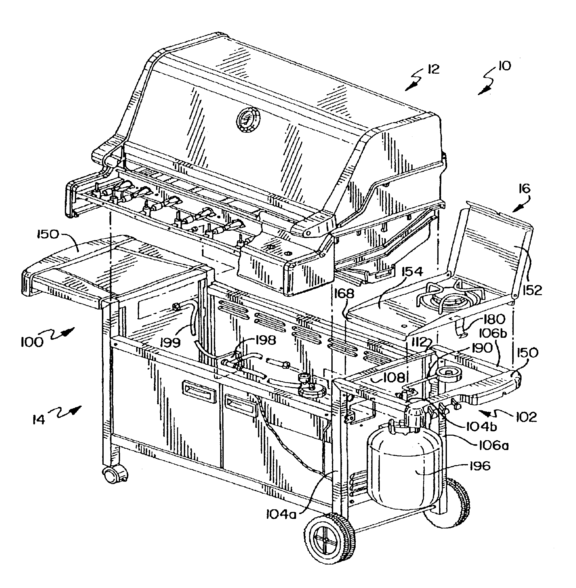
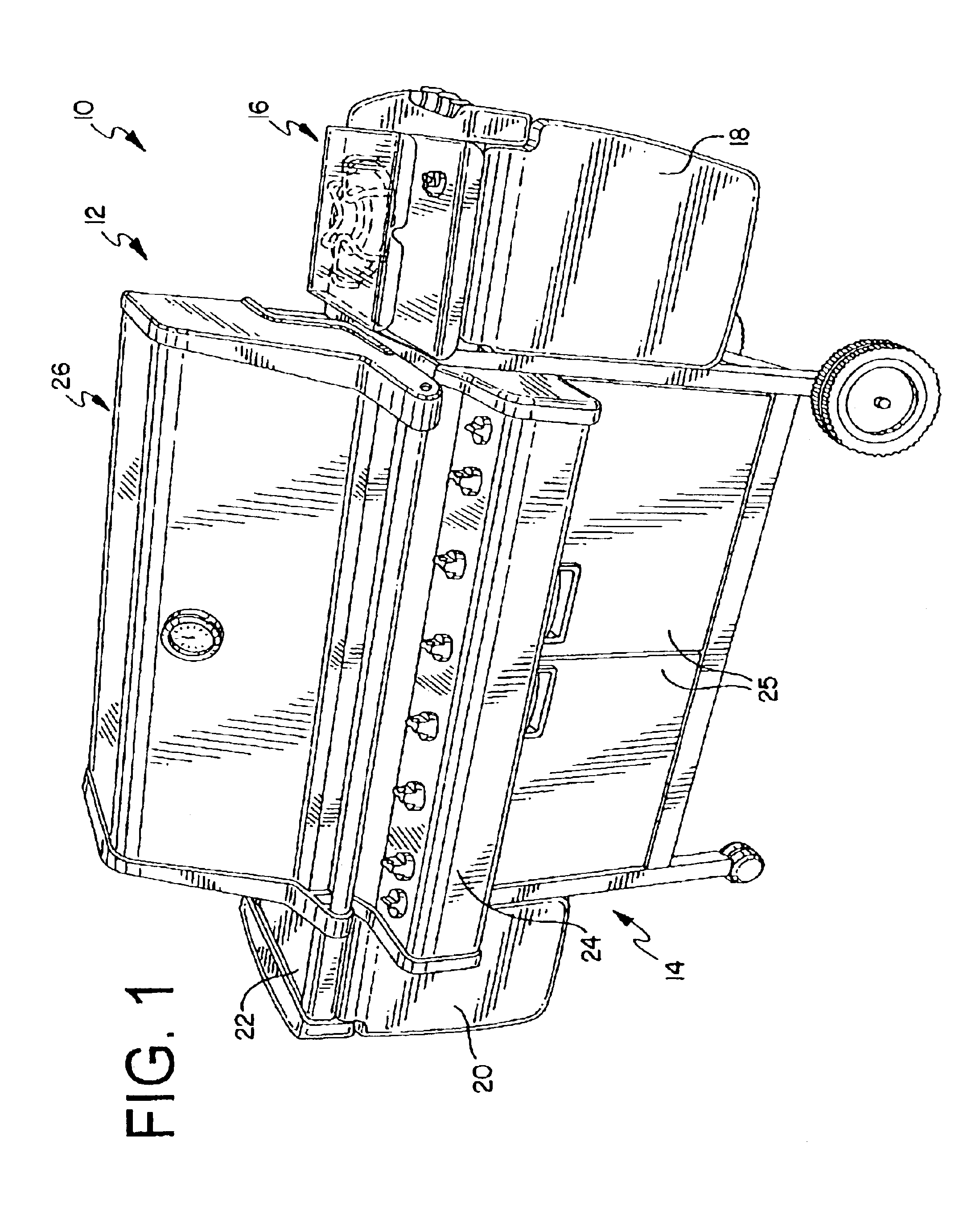
[0030]A barbecue grill assembly 10 is shown in FIG. 1. The barbecue grill assembly 10 generally includes a cooking chamber 12 and a support frame assembly 14. The frame assembly 14 is configured to provide support to the cooking chamber 12. The barbecue grill assembly 10 further includes an auxiliary burner 16, collapsible work surfaces 18, 20, and a fixed work surface 22. A control panel 24 is removably secured to a front portion of the cooking chamber 12. A pair of doors 25 are operably connected to the support frame assembly 14. The support frame assembly 14 may include a re...


PUM


Abstract

The present invention provides a barbecue grill assembly with a support frame assembly including a left and right frame assembly. These frame assemblies are formed from a front frame member, a rear frame member, and a side member that connects the front and rear frame members. The grill assembly can have a first and a second horizontal member to connect the frame members of the left and right frame assemblies. The barbecue grill assembly further comprises a cooking chamber with a cover hingeably connected to a firebox. The firebox has a pair of opposed end walls with a mounting assembly that engages a limited extent of the front and rear frame members when the cooking chamber is connected to the support frame assembly. The end wall also have extending rails that define a channel configured to house conduit and fuel lines. Preferably, the left and right frame assemblies are pre-welded to facilitate assembly of the barbecue grill assembly.

Description

CROSS-REFERENCE TO RELATED APPLICATIONS[0001]This Application claims the benefit of Provisional Application No. 60 / 380,755, filed on May 15, 2002.FEDERALLY SPONSORED RESEARCH OR DEVELOPMENT[0002]Not Applicable.TECHNICAL FIELD[0003]The present invention relates to a barbecue grill assembly. More specifically, the present invention relates to a barbecue grill assembly with a cooking chamber that engages a limited portion of the support frame assembly.BACKGROUND OF THE INVENTION[0004]The popularity of gas barbecue grills and gas outdoor cooking devices has increased tremendously over the last twenty-five years. Conventional barbecue grills include a cooking chamber and a frame assembly that supports the cooking chamber. Typically, the cooking chamber has a cast bottom and a cast cover. In general terms, the frame assembly includes a plurality of frame members including vertical, horizontal, and transverse members. An example of the conventional design is shown in U.S. Pat. No. 5,109,83...

Claims


Application Information

Patent Timeline
Patent Type & Authority Patents(United States)
IPC IPC(8): A47J37/07
CPCA47J37/0704
Inventor BRUNO, ADRIAN A.CHOI, DANIEL S.ALDEN, J. MICHAELSTEPHEN, JAMES C.
Owner WEBER-STEPHEN PRODUCTS
Why Eureka
Try Eureka