Air baffle for managing cooling air re-circulation in an electronic system

a technology for electronic systems and air baffles, which is applied in the direction of cooling/ventilation/heating modifications, electrical apparatus casings/cabinets/drawers, instruments, etc., can solve the problems of significant heat generation of electronic equipment contained within the enclosure, significant thermal management difficulties of low-profile computer system installations, and the like. to achieve the effect of reducing or eliminating the recirculation of heated exhaust air

Active Publication Date: 2005-08-09
HEWLETT-PACKARD ENTERPRISE DEV LP
View PDF16 Cites 34 Cited by
  • Summary
  • Abstract
  • Description
  • Claims
  • Application Information

AI Technical Summary

Benefits of technology

[0004]What are desired are an apparatus and operating method that reduce or eliminate re-circulation of heated exhaust air from an electronic device.

Problems solved by technology

Electronic equipment contained within the enclosure generates a significant amount of heat.
Thermal damage may occur to the electronic equipment unless the heat is removed.
Low-profile computer system installations present significant thermal management difficulties.
However, an unimpeded and direct airflow path exists between the enclosure inlet and exit allowing hot exhaust air to re-circulate from the devices to the inlet vent, a problem that is exacerbated by cable blockage of airflow exiting the rear of the enclosure.
Re-circulation of heated air can create thermal difficulties that may result in system overheating and failure.
If airflow patterns allow re-usage of air that is previously heated by electronic equipment, attempts to cool electronic equipment can fail and less effective heat transfer from the equipment to the cooling airflow can result.
In some circumstances insufficient heat transfer can take place and the equipment may overheat and potentially sustain thermal damage.

Method used


Image

  • Air baffle for managing cooling air re-circulation in an electronic system
  • Air baffle for managing cooling air re-circulation in an electronic system
  • Air baffle for managing cooling air re-circulation in an electronic system

Examples


Embodiment Construction

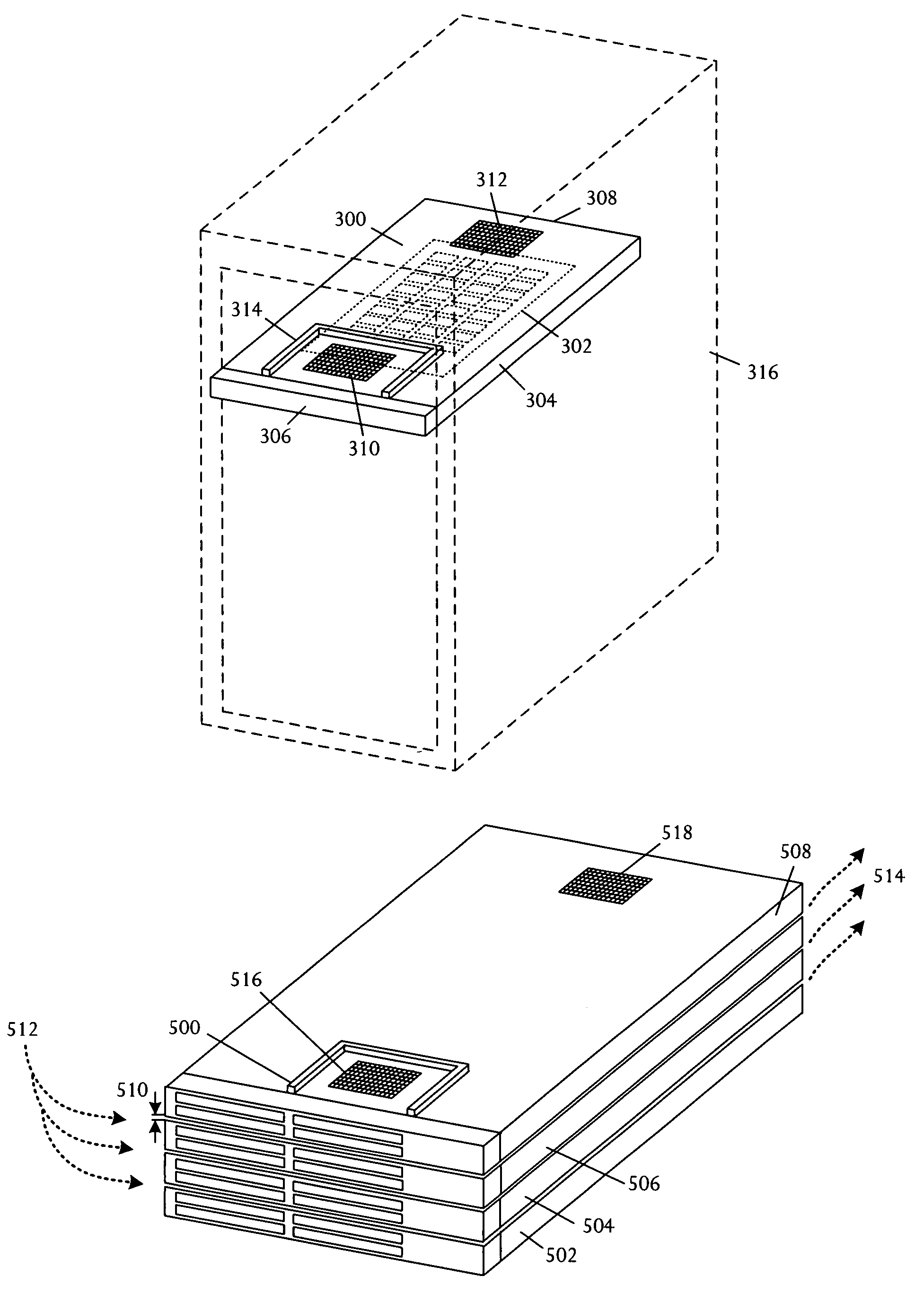
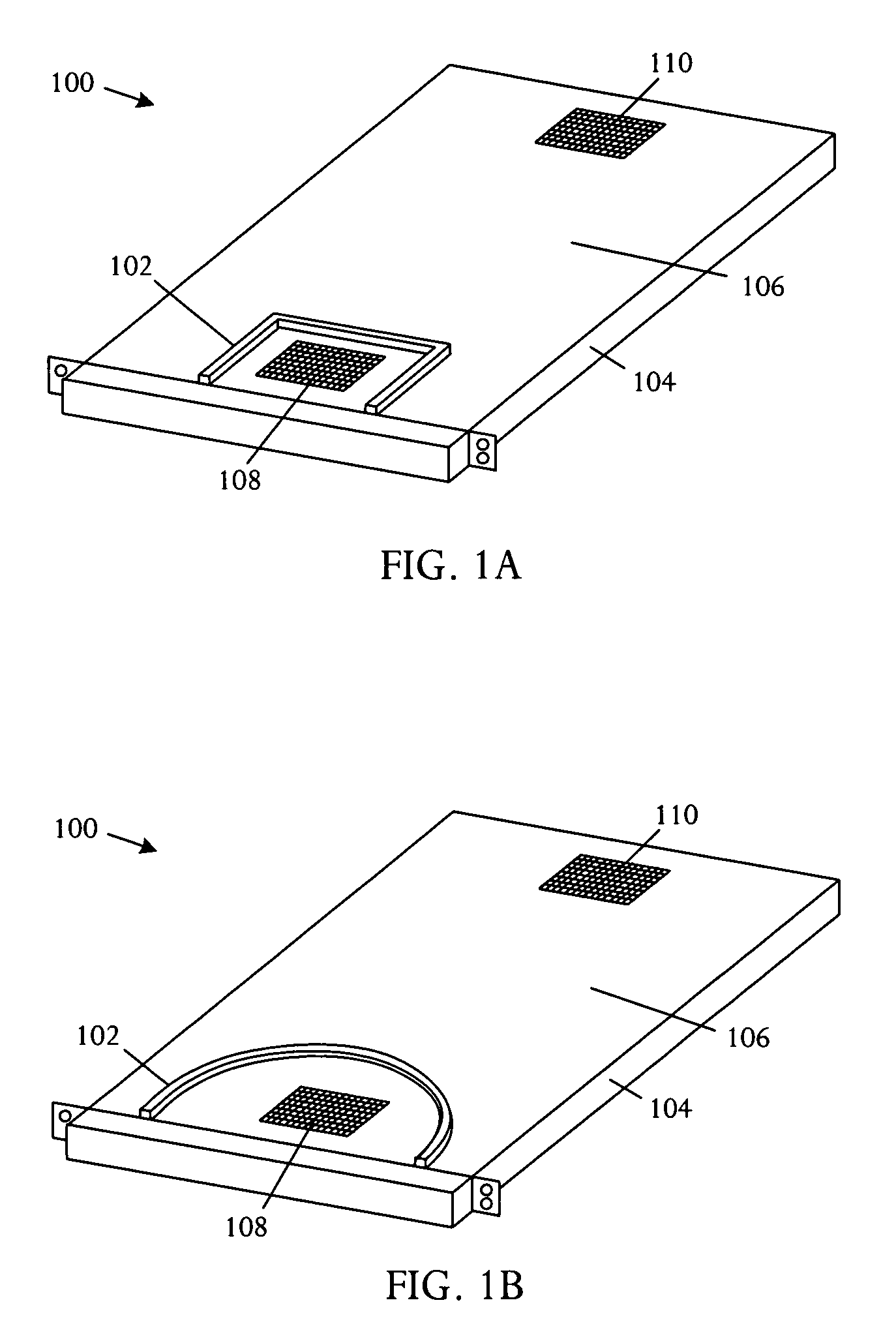
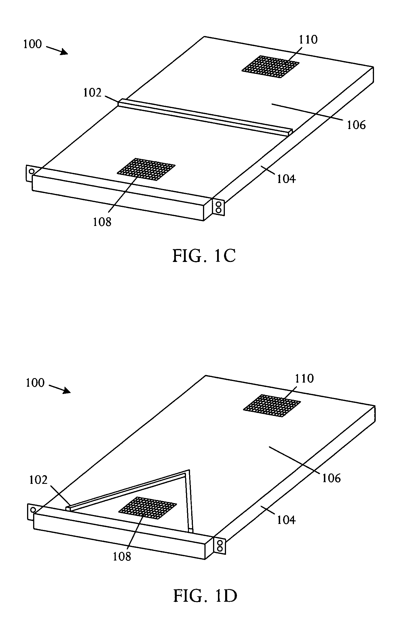
[0017]In a system with a fully loaded cabinet or rack, each rack-mounted device in the rack is adjacent to an overlying device or surface. A baffle can be mounted upon the chassis of an electronic device to obstruct air flow in the space between inlet and exhaust vents on the surface of the chassis. The baffle is typically flexible, for example manufactured from materials such as closed-cell foam rubber, and can extend vertically to make contact with the overlying device or other overlying surface. Flexibility of the baffle allows compliance to account for variation, or tolerance, of the gap dimension between devices and surfaces.

[0018]The flexible air baffle contacts the underside of the overlying surface, either of an electronic device mounted directly above, or other planar surface, creating an obstruction between the inlet and exhaust vents of the electronic device. The obstruction ensures that air entering the inlet vent is from the front of the rack, preventing re-circulation ...


PUM


Abstract

An airflow management apparatus is used in an electronic system and includes a flexible air baffle that mounts on a chassis of an electronic device in an arrangement and obstructs air flow between an air inlet vent and an air exhaust vent of the electronic device. The flexible air baffle has a thickness that extends across a gap to contact an adjacent vertically-stacked electronic device.

Description

BACKGROUND OF THE INVENTION[0001]Electronic systems and equipment such as computer systems, network interfaces, storage systems, and telecommunications equipment are commonly enclosed within a cabinet or housing for support, physical security, and efficient usage of space. Electronic equipment contained within the enclosure generates a significant amount of heat. Thermal damage may occur to the electronic equipment unless the heat is removed.[0002]Low-profile computer system installations present significant thermal management difficulties. For example, Electronics Industry Association (EIA) standard racks are commonly used to house electronic equipment. In relatively large systems, for example 2U or larger where “U” is the measuring unit for racks and rack-mountable components with 1U=1.75″ or 44.45 mm, most cooling air enters through the front of the enclosure and exits through the rear. For low-profile systems, the enclosure front is significantly blocked by hard drives and media...

Claims


Application Information

Patent Timeline
Patent Type & Authority Patents(United States)
IPC IPC(8): H05K7/20
CPCH05K7/20727
Inventor MALONE, CHRISTOPHER G.SIMON, GLENN C.
Owner HEWLETT-PACKARD ENTERPRISE DEV LP
Why Eureka
Try Eureka