Slot filler with capability to control electronic cooling air recirculation

a technology of electronic cooling air and slot filler, which is applied in the direction of cooling/ventilation/heating modifications, electrical apparatus casings/cabinets/drawers, instruments, etc., can solve the problems of significant thermal management difficulties for low-profile computer system installations, electrical equipment contained within enclosures that generate a significant amount of heat, etc., to reduce or eliminate the recirculation of heated exhaust air

Inactive Publication Date: 2005-07-21
HEWLETT PACKARD DEV CO LP
View PDF16 Cites 28 Cited by
  • Summary
  • Abstract
  • Description
  • Claims
  • Application Information

AI Technical Summary

Benefits of technology

[0006] What are desired are an apparatus and operating method that reduce or eliminate re-circulation of heated exhaust air from electronic devices.

Problems solved by technology

Electronic equipment contained within the enclosure generates a significant amount of heat.
Thermal damage may occur to the electronic equipment unless the heat is removed.
Low-profile computer system installations present significant thermal management difficulties.
If airflow patterns allow re-usage of air that is previously heated by electronic equipment, attempts to cool electronic equipment can fail and less effective heat transfer from the equipment to the cooling airflow can result.
In some circumstances insufficient heat transfer can take place and the equipment may overheat and potentially sustain thermal damage.
If an open space is interposed in a slot above an electronic device, hot air exhausted from the device may re-circulate back to the vicinity of the air inlet, greatly impacting thermal management for device.
Given the power densities of 1U and 2U electronic equipment and the challenges of effectively attaining room-level cooling for these devices, racks are commonly underpopulated.

Method used


Image

  • Slot filler with capability to control electronic cooling air recirculation
  • Slot filler with capability to control electronic cooling air recirculation
  • Slot filler with capability to control electronic cooling air recirculation

Examples


Embodiment Construction

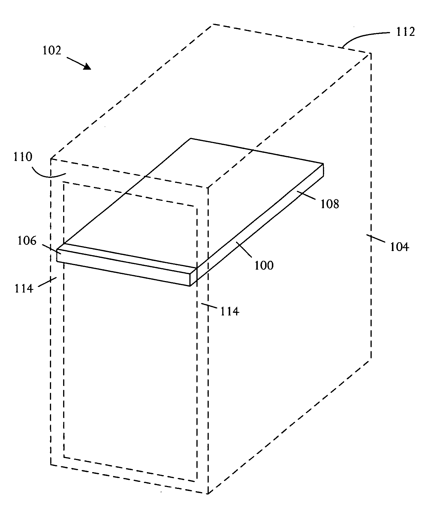
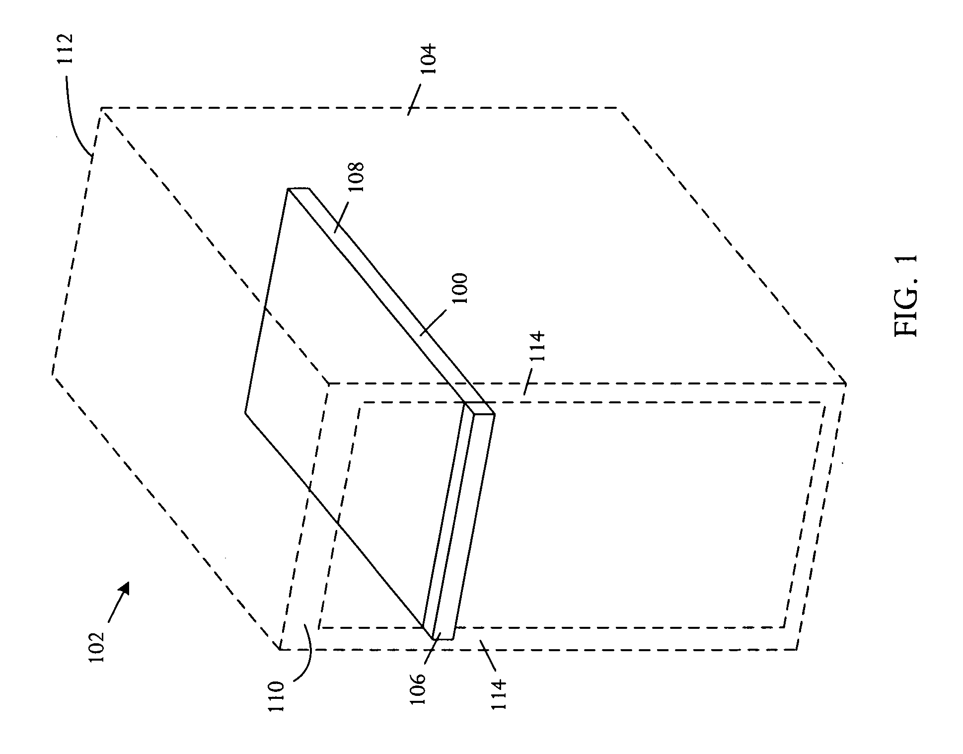
[0019] A slot filler comprising a filler panel and a body or member that couples to the filler panel prevents or substantially reduces re-circulation of heated air in an electronic system. The body or member, for example a sheet metal or plastic piece, extends into the rack a length that approximates the length of a typical rack-mounted electronic device, for example approximately 26 inches for a standard EIA rack. In some examples, the body or member may form a box structure, approximately 1U in height, extending approximately 26 inches in depth into the rack or cabinet. In other embodiments, the body may be a thin piece of material, anchored to the cabinet front panel, with suitable rigidity and strength to maintain a high air flow resistance within the enclosure. The body can be fabricated in a manner that the length is adjustable to accommodate adjacent products with different lengths. Various common adjustment techniques may be used. The slot filler emulates the effect on air f...


PUM


Abstract

A slot filler for usage in a rack cabinet can accept a plurality of stacked electronic devices. The cabinet has an air inlet and exit on mutually opposing sides and a plurality of slots capable of securing the stacked electronic devices. The slot filler comprises a blanking panel capable of covering an entry opening of a slot that is unoccupied by an electronic device, and a body coupled to the blanking panel that emulates dimensions of an electronic device and has a thickness selected so that clearance between the slot filler and an adjacent electronic device leaves an air flow gap from the air inlet to exit that is sufficiently small to create an air flow resistance preventing air from re-circling toward the air inlet.

Description

BACKGROUND OF THE INVENTION [0001] Electronic systems and equipment such as computer systems, network interfaces, storage systems, and telecommunications equipment are commonly enclosed within a cabinet or housing for support, physical security, and efficient usage of space. Electronic equipment contained within the enclosure generates a significant amount of heat. Thermal damage may occur to the electronic equipment unless the heat is removed. [0002] Low-profile computer system installations present significant thermal management difficulties. For example, Electronics Industry Association (EIA) standard racks are commonly used to house electronic equipment. In relatively large systems, for example 2U or larger where “U” is the measuring unit for racks and rack-mountable components with 1U=1.75″ or 44.45 mm, most cooling air enters through the front of the enclosure and exits through the rear. For low-profile systems, the enclosure front is significantly blocked by hard drives and m...

Claims


Application Information

Patent Timeline
Patent Type & Authority Applications(United States)
IPC IPC(8): G06F1/20H05K5/00H05K7/20
CPCH05K7/20563
Inventor MALONE, CHRISTOPHER G.SIMON, GLENN C.
Owner HEWLETT PACKARD DEV CO LP
Why Eureka
Try Eureka