Combination utility knife

a utility knife and combination technology, applied in the field of multi-functional utility knives, can solve the problems of inconvenient carrying of a knife and a pencil, inability to cut into hard materials such as cardboard, and the same knife blade may not be suitable for cutting strings, ropes, wires,

a utility knife and combination technology, applied in the field of multi-functional utility knives, can solve the problems of inconvenient carrying of a knife and a pencil, inability to cut into hard materials such as cardboard, and the same knife blade may not be suitable for cutting strings, ropes, wires,

US6938345B2Inactive Publication Date: 2005-09-06YU ZU SHENG

Image

  • Combination utility knife
  • Combination utility knife
  • Combination utility knife

Examples


Embodiment Construction

[0017]Preferred embodiments of the present invention will now be described hereinafter with reference to the accompanying drawings. The present invention may, however, be embodied in many different forms and should not be construed as limited to the embodiments set forth herein.

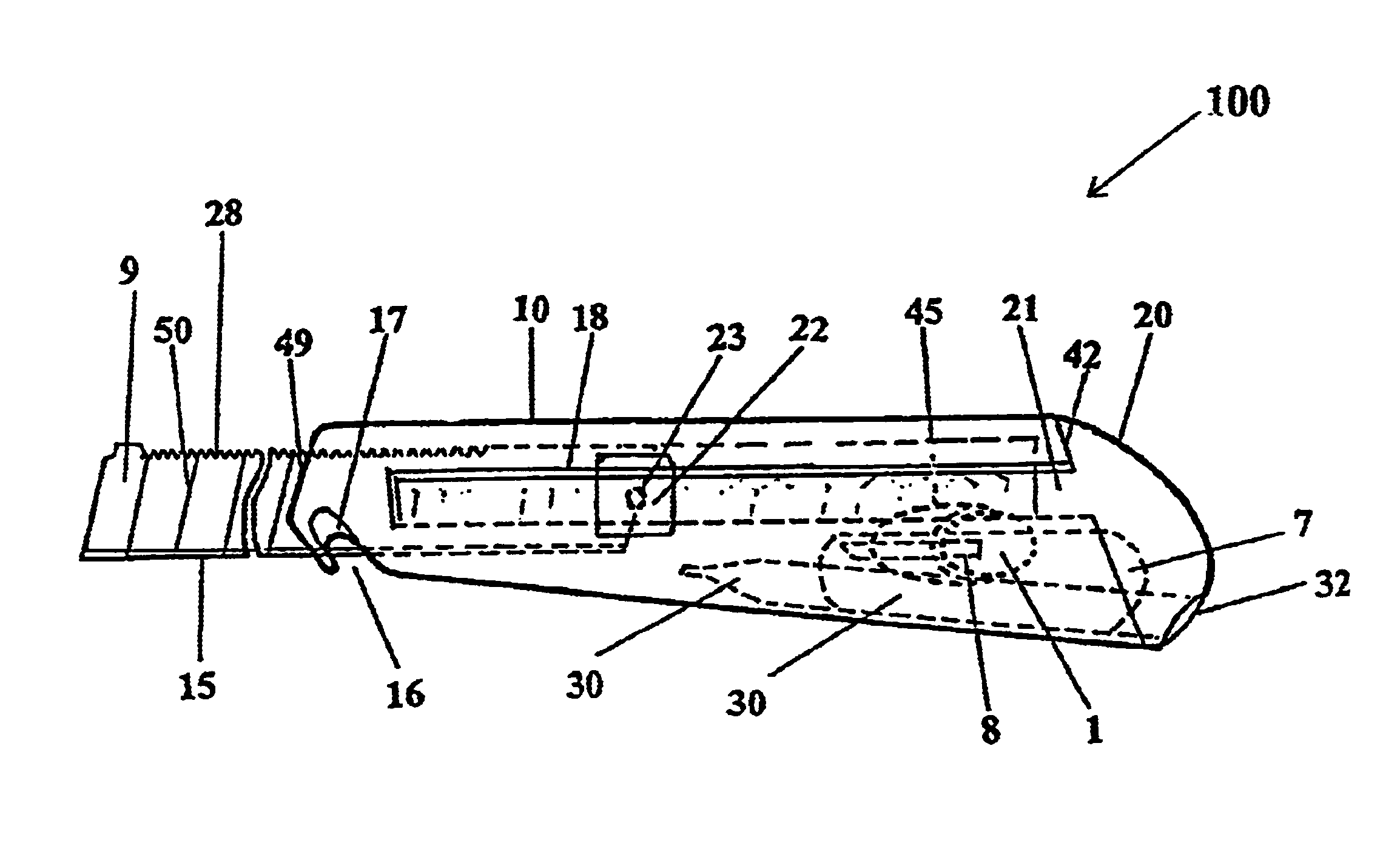
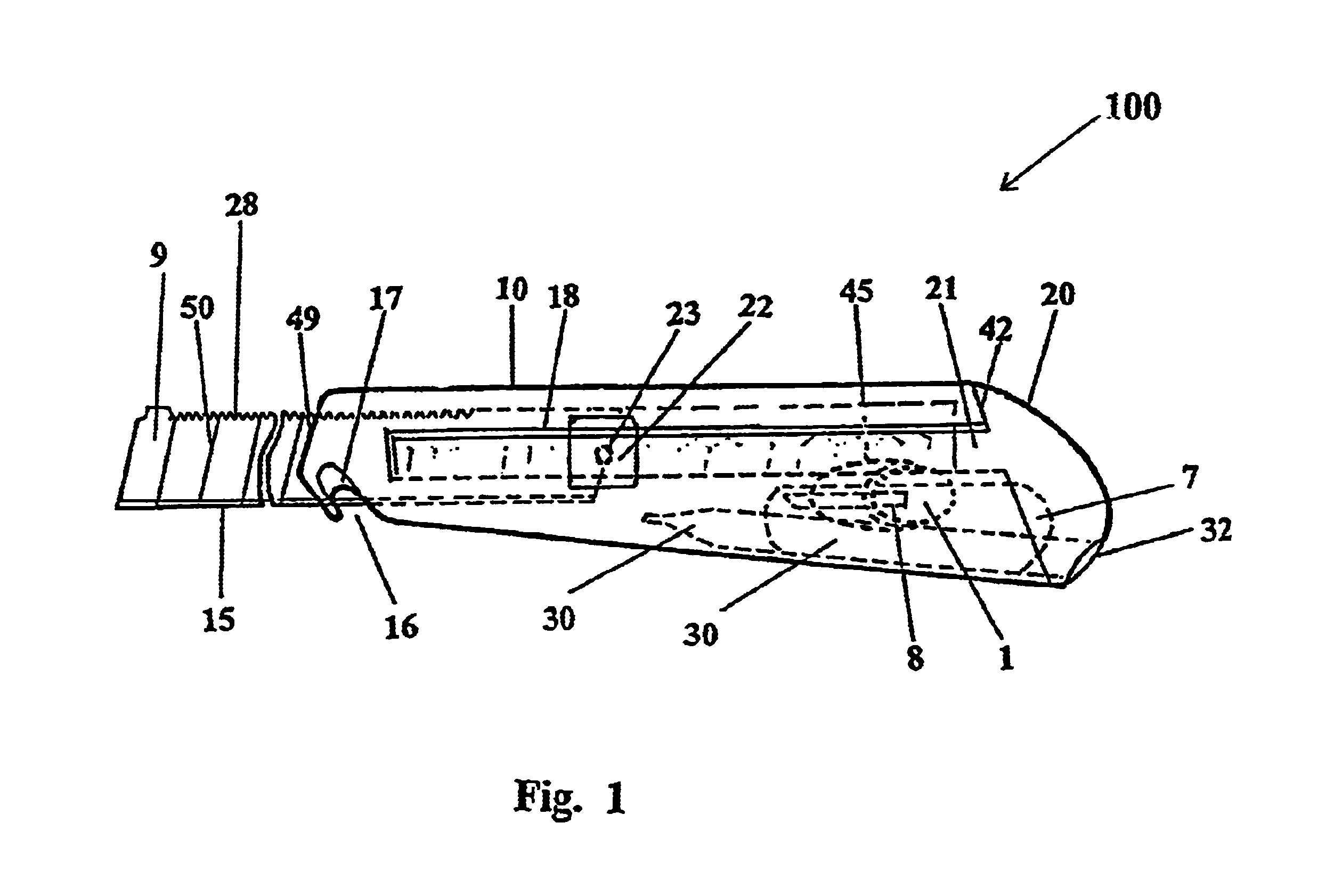
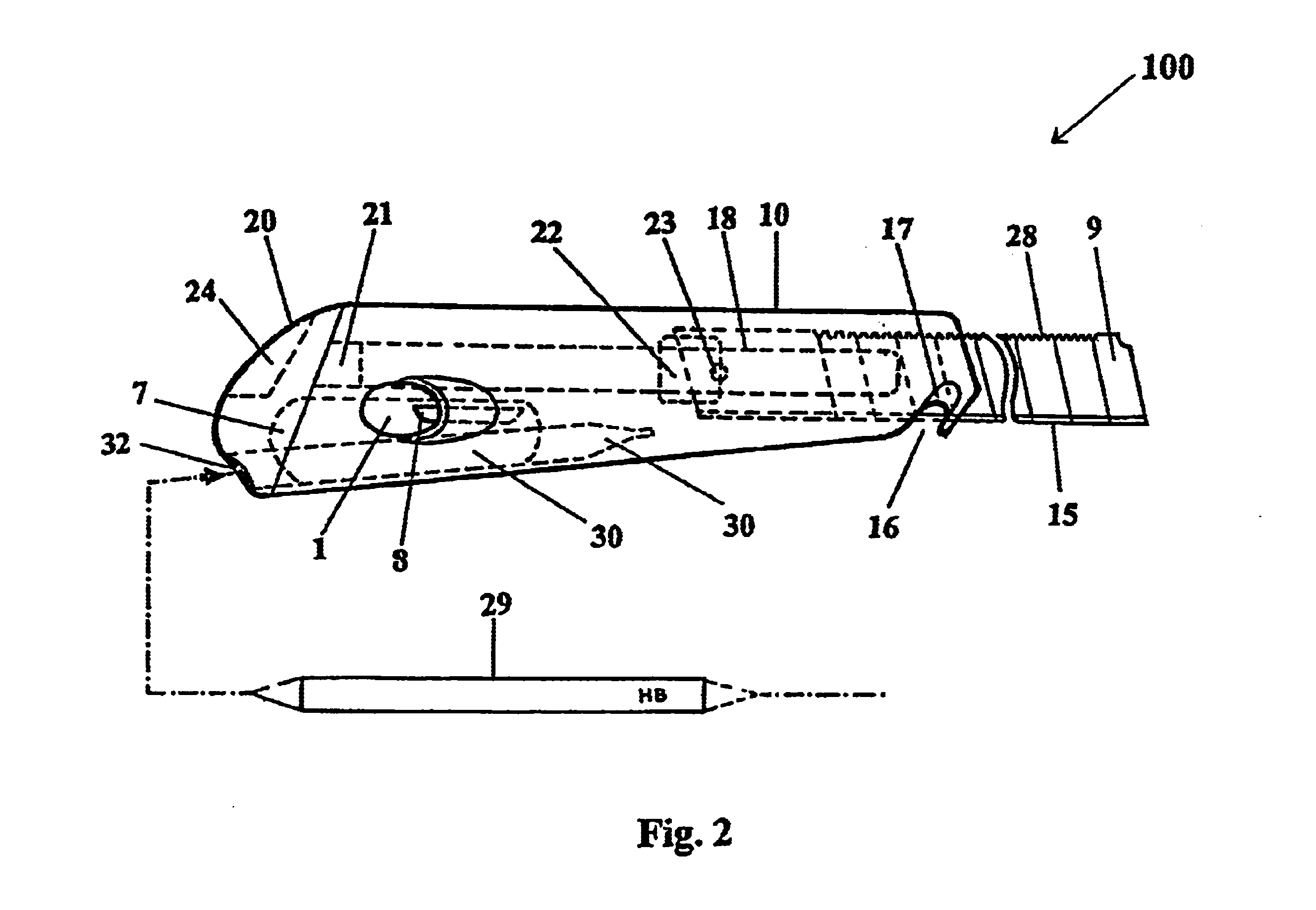
[0018]Referring to FIGS. 1, 2, 3, 4(a), and 4(b), there is illustrated a retractable utility knife according to an embodiment of the present invention. FIG. 1 is a left side view of a utility knife when a retractable blade is extended out of a knife housing according to an embodiment of the present invention. FIG. 2 is a right side view of a utility knife when a retractable blade is extended out of the housing according to an embodiment of the present invention.

[0019]The utility knife100 includes a blade 9 and a knife housing 10 molded as a unitary structure using suitable materials such as plastics or metals.

[0020]The knife housing 10 has a carrier groove 18, extending to the right hand end 42. The blade 9 o...


PUM


Abstract

A retractable blade utility knife includes a knife housing, a blade, a pencil housing, a pencil sharpening slot, and a rear cover. The knife may further include a rope-cutting recess and a cutting surface in a lower end and a sawing surface in an upper end of the blade. The pencil housing forms in a lower rear part of the knife housing to keep hold of a pencil. The pencil sharpening slot is connected to a conical bore and a pencil chips storage room. The rope-cutting recess facilitates rope cutting by the blade. The blade carrier carries the blade and slides along a longitudinal axis of a knife groove formed in one side of the knife housing. The rear cover of the knife includes a pencil inlet hole and a rear cover fixed switch. The rear cover is detachably coupled to a rear portion of the knife housing via the rear cover fixed switch. The rear cover includes a pencil chip storage space and a pencil chip outlet.

Description

BACKGROUND[0001]1. Field of the Invention[0002]The present invention relates to a multifunction utility knife and, more particularly, to a utility knife with one or more pencil, a pencil-sharpening slot, and a blade with an opposing saw tooth.[0003]2. Discussion of Related Art[0004]Utility knives having a fixed blade lock blades into a fixed, often non-retractable position of a knife housing. In comparison with the fixed blade knives, retractable blade knives offer the convenience of being able to quickly adjust the cutting depth of the blades as well as safe usage of allowing the blade to be retracted completely into a knife housing when not in use. Typically, the retractable blade knives include a knife housing and a blade, which is retracted into the knife housing.[0005]Retractable blade knives are often used by construction workmen or artists to cut a workpiece into various shapes. The user is likely to use a marker such as a pencil to mark or draw on a work piece prior to cutti...

Claims


Application Information

Patent Timeline
06 Sep 2005
Publication
US6938345B2
IPC
B23D61/00; B23D61/12; B26B5/00; B26B11/00; B26B9/00; B26B9/02; B43K29/00; B43K29/18; B43L23/08
CPC
B23D61/12; B26B5/002; B26B9/02; B26B11/00; B43K29/004; B43K29/18; B43L23/08
Inventors
YU, ZU SHENG