Grate furnace

a furnace and grate technology, applied in the direction of grates, combustion process, lighting and heating equipment, etc., can solve the problems of difficult sealing of drive links, complicated or made more difficult multiple-path arrangements, and disadvantageous consequences

Inactive Publication Date: 2005-09-06
MARTIN GMBH FUR UMWELT UND ENERGIETECHNIK
View PDF9 Cites 7 Cited by
  • Summary
  • Abstract
  • Description
  • Claims
  • Application Information

AI Technical Summary

Benefits of technology

[0019]When, in an another advantageous embodiment of the invention, each housing is connected to its assigned under-grate blast chamber by an opening which can be sealed with a flap, it is possible to turn off the u...

Problems solved by technology

In a first variant, these devices were then located at the side next to the actual grate module, which complicated or made more difficult a multiple-path arrangement of these grate modules next to one another and required drive linkages which were difficult to seal.
When, according to a second variant, the drive devices were located under the grate, there were always disadvantageous co...

Method used


Image

  • Grate furnace
  • Grate furnace
  • Grate furnace

Examples


Embodiment Construction

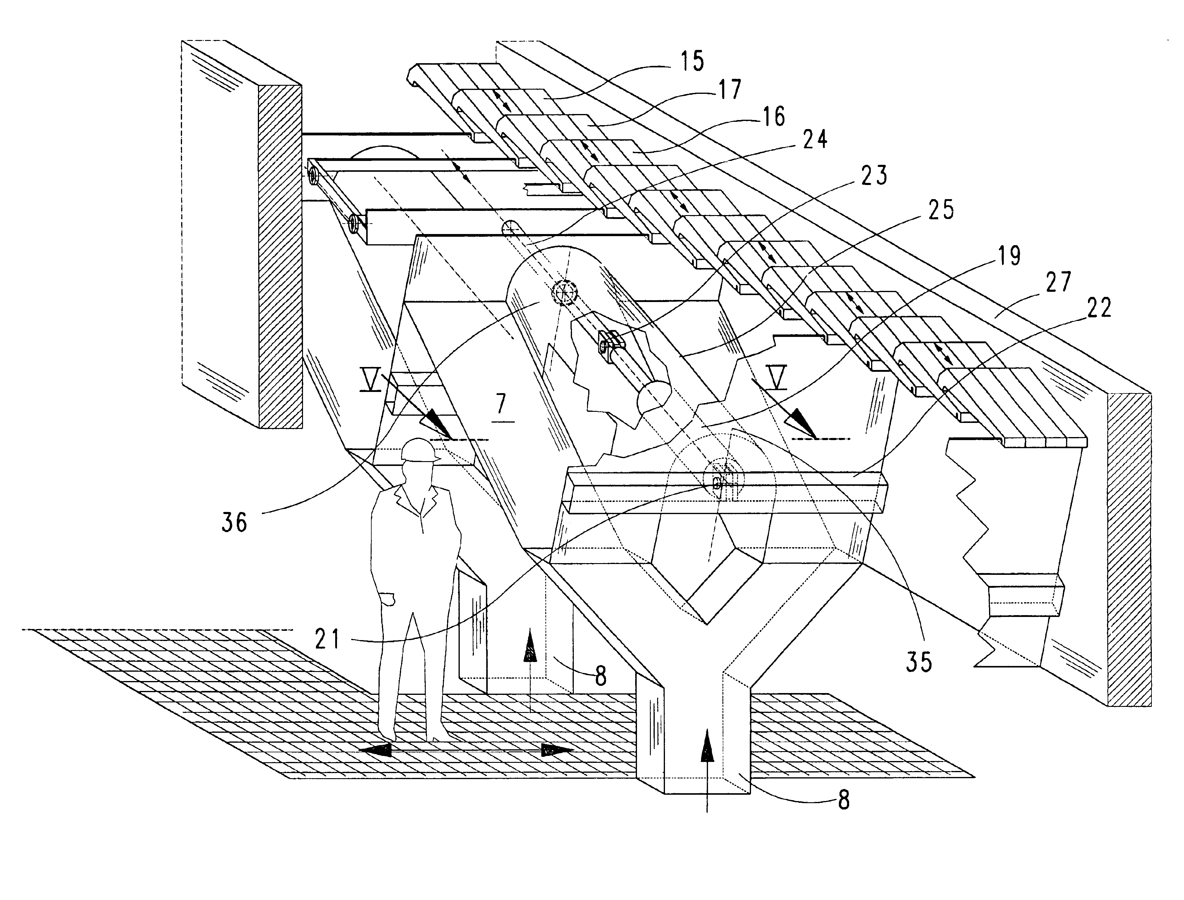
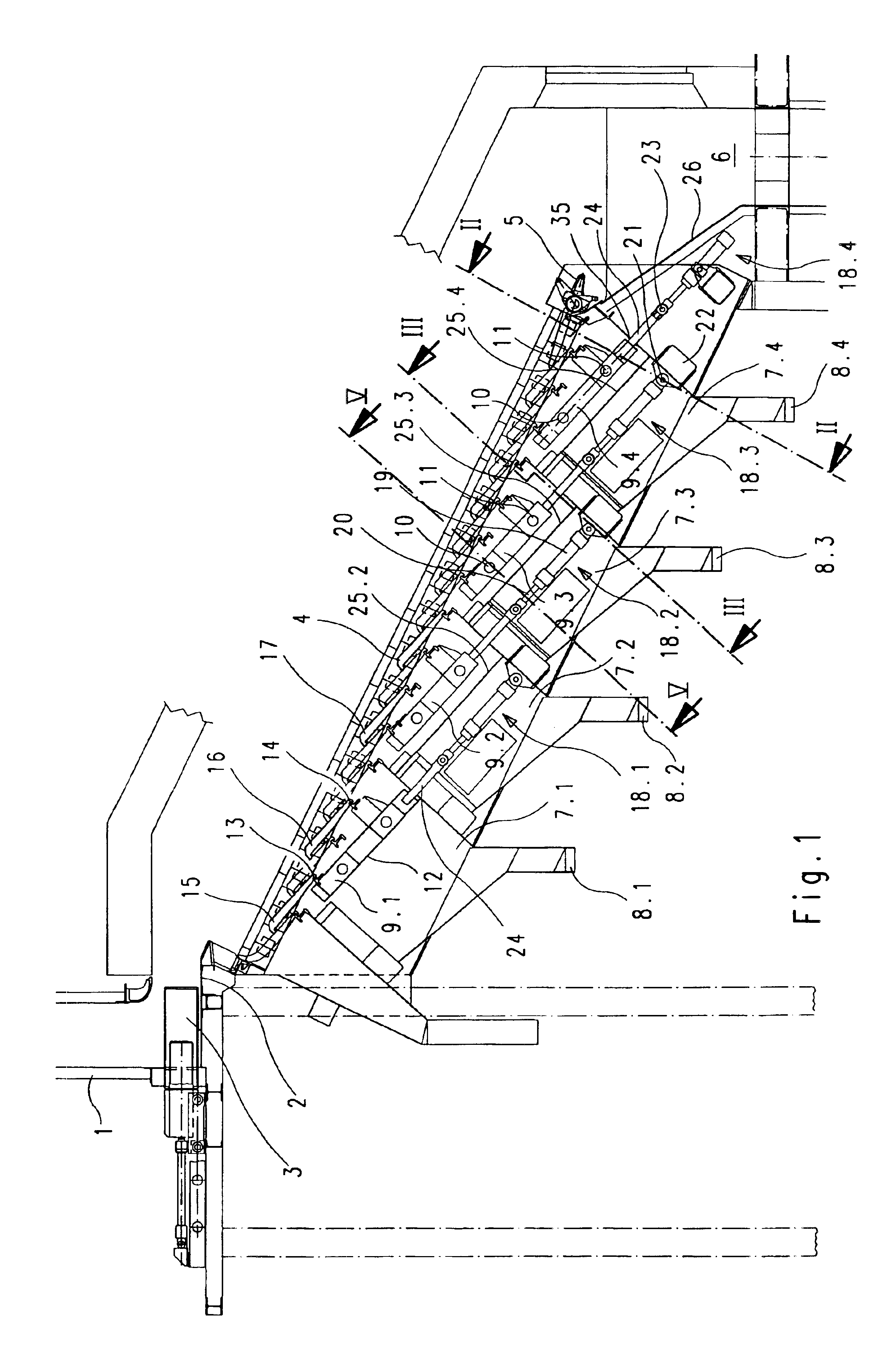
[0026]A grate furnace according to FIG. 1 comprises a charging hopper 1, a charging device 3 which can move to and fro over a charging table 2, a grate 4, a collecting device 5 arranged at the end of the grate for collecting the ash, and an ash chute 6 into which the burnt ash falls.

[0027]Situated under the grate 4 are four mutually separate underblast chambers 7.1, 7.2, 7.3 and 7.4. These underblast chambers each have connections 8.1 to 8.4 for the separate supply of primary air, which is blown toward the grate 4 from the underside and through the grate into the fuel lying on the grate, for example refuse.

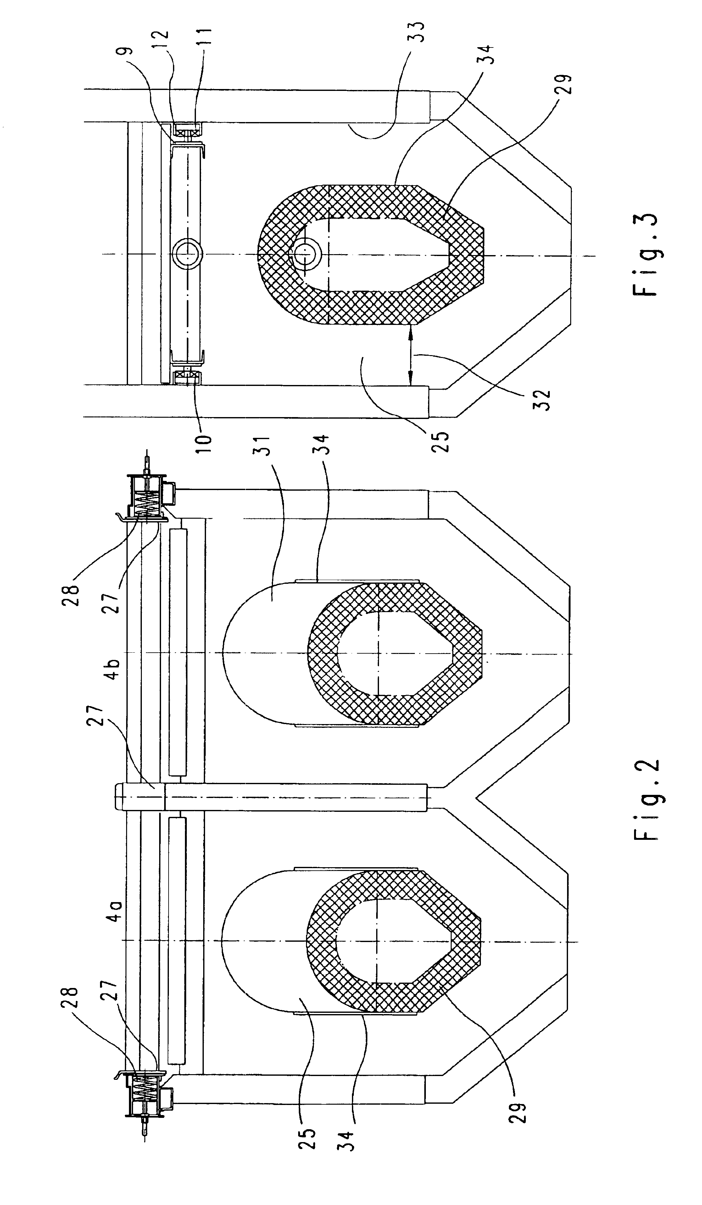
[0028]The underblast chambers are arranged in a stepped staggered manner in relation to one another following the inclined grate 4. Arranged above each underblast chamber is a carriage 9.1 to 9.4 which, as can be seen in connection with FIG. 3 in particular, is in each case provided with two roller pairs 10 and 11 which are guided in guide tracks 12. Arranged on each carriage are ...


PUM


Abstract

A grate furnace with a grate includes grate steps made of grate elements lying next to one another. Every second grate step in the longitudinal direction of the grate can be driven for carrying out stoking movements and the grate steps in each case lying therebetween are stationary. Drive devices for driving the moveable grates are arranged in housing chambers and are in this way protected against impairment caused by material falling through the grate. A certain section of the housing chamber is open toward the bottom so that it is accessible even during operation of the grate furnace.

Description

PRIORITY CLAIM[0001]This is a Continuation-in-Part of U.S. patent application Ser. No. 10 / 210,156 which was filed Aug. 1, 2002 now abandoned. Priority is claimed on that application under 35 U.S.C. §120. Priority is also claimed on the following foreign application under 35 U.S.C. §119, Country: Germany, Application No.: 101 37 520.4, Filed: Aug. 1, 2001.BACKGROUND OF THE INVENTION[0002]1. Field of the Invention[0003]The invention relates to a grate furnace with a grate having grate steps including grate elements lying next to one another, every second grate step in the longitudinal direction of the grate can be driven for carrying out stoking movements and the grate steps in each case lying therebetween are stationary, the drive devices for the movable grate steps being arranged under the grate.[0004]2. Description of the Prior Art[0005]Known grates of grate furnaces with alternately arranged fixed and movable grate steps had a continuous stepped beam under the grate, to which beam...

Claims


Application Information

Patent Timeline
IPC IPC(8): F23H7/00F23H17/00F23H7/08
CPCF23H7/08F23H17/00
Inventor MARTIN, JOHANNESWEBER, PETERFAMILLER, WERNER
Owner MARTIN GMBH FUR UMWELT UND ENERGIETECHNIK
Why Eureka
Try Eureka