Hook capable of hooking chain at desired length

a hook and chain technology, applied in the field of hooks, can solve problems such as unstable and dangerous

Inactive Publication Date: 2005-09-13
HUNG RUNG TE
View PDF8 Cites 13 Cited by
  • Summary
  • Abstract
  • Description
  • Claims
  • Application Information

AI Technical Summary

Benefits of technology

[0003]Accordingly, the primary object of the present invention is to provide a hook capable of hooking a chain at a desired length. The hook comprises a hook body, and a buckle above the hook body. The buckle has a U shape opening. Width of the shape opening is confined by the size of a chain to be hung. The buckle has a penetrating groove which penetrates two inner sides of the buckle and one outer side of the buckle. A spring and a movable shaft pass through the penetrating groove. The movable shaft is positioned by a pin so that the spring is compressed by the movable shaft and the movable shaft will not drop out of the buckle. A notch is formed at a predetermined portion of the movable shaft. A semi-round groove is formed at a coupling portion of the buckle and the notch, and the semi-round groove is positioned across the two inner sides of the buckle.

Problems solved by technology

However other than preparing the U shape hook or the bi-directional hook in advance, the U shape hook or the bi-directional hook will vibrate so that it is unstable and dangerous.

Method used


Image

  • Hook capable of hooking chain at desired length
  • Hook capable of hooking chain at desired length
  • Hook capable of hooking chain at desired length

Examples


Embodiment Construction

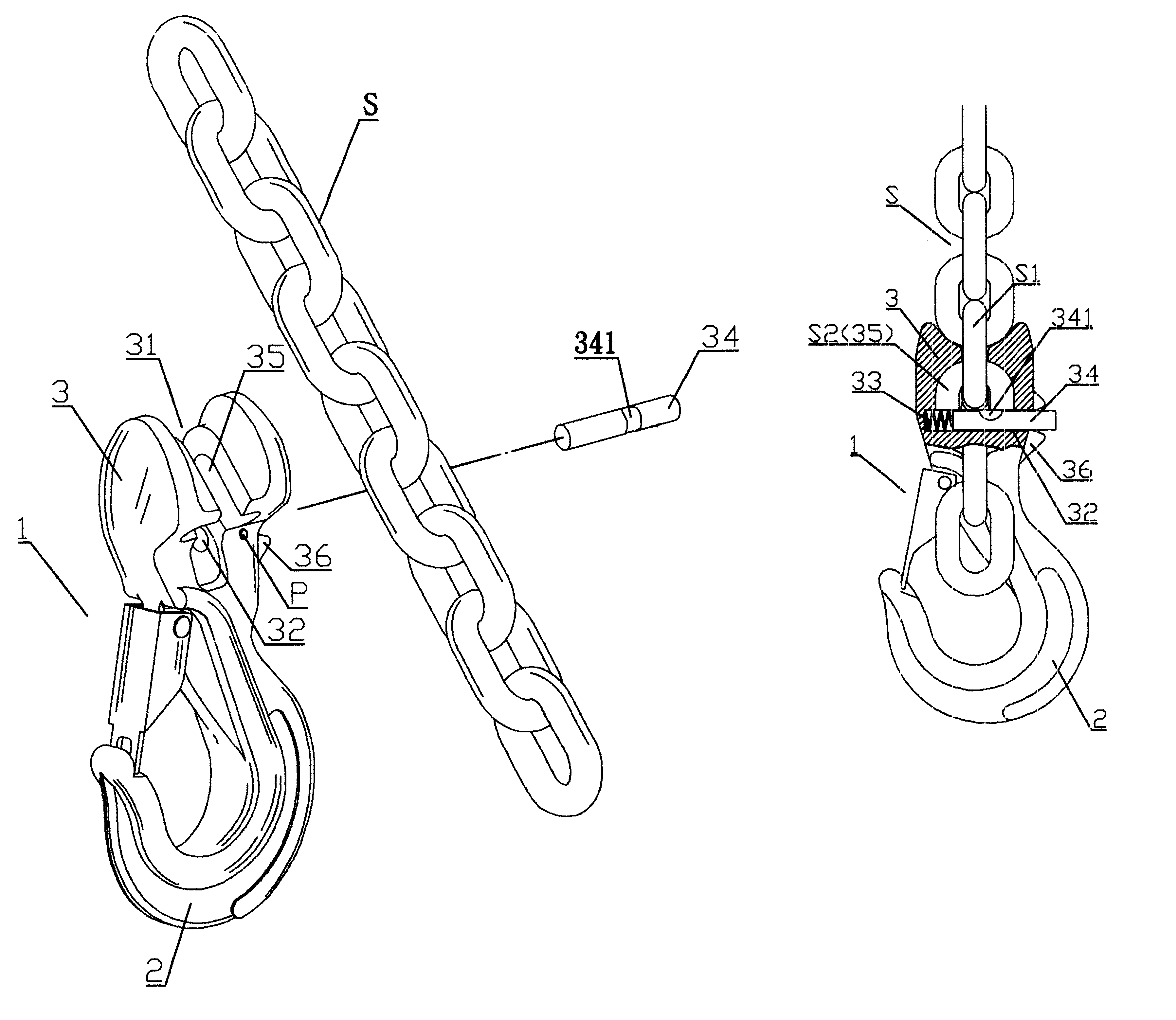
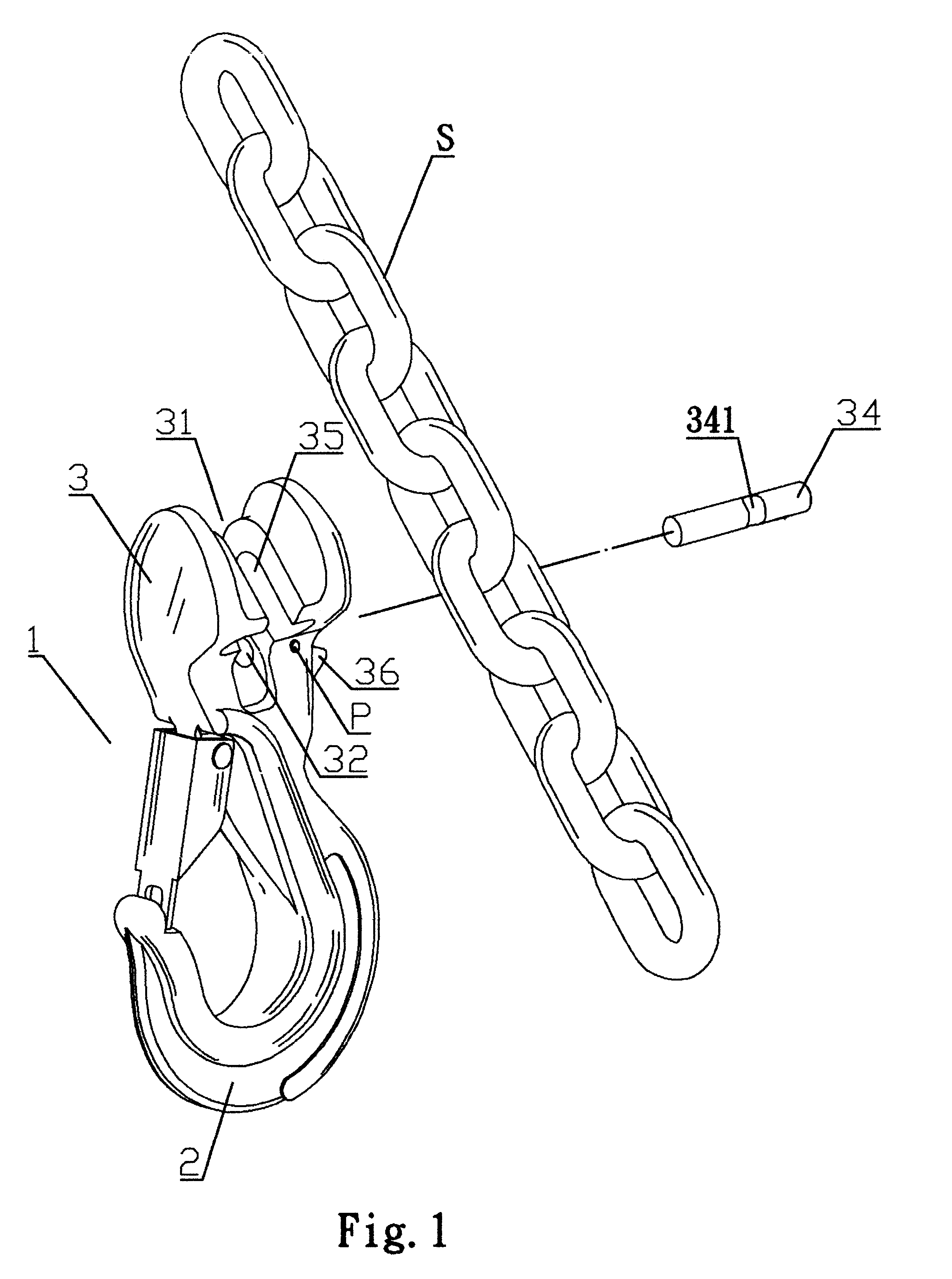
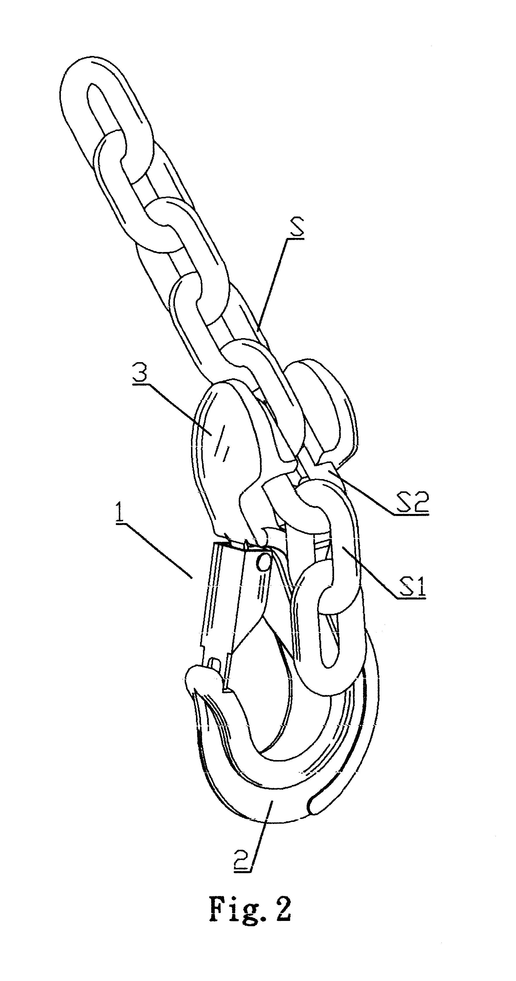
[0012]Referring to FIGS. 1 and 2, the structure of the present invention is illustrated. The present invention is formed by a hook body 2 and a buckle 3 above the hook body 2.

[0013]The buckle 3 has a U shape opening 31. A width of the U shape opening 31 is confined by the size of the chain to be suspended from the hook. The buckle 3 has a penetrating groove 32 which penetrating two inner sides of the buckle 3 and one outer side of the buckle 3.

[0014]Referring to FIG. 4-A and FIG. 4-B, a spring 33 and a movable shaft 34 passes through the penetrating groove 32. The spring 33 is positioned at an inner side. The movable shaft 34 is positioned by a pin P (see FIG. 1) so that the spring 33 and the movable shaft 34 will not drop out of the buckle 3. A notch 341 is formed at a predetermined portion of the movable shaft 34.

[0015]A semi-round groove 35 is formed at a coupling portion of the buckle 3 and the notch 341 and the semi-round groove 35 runs across the two inner sides of the buckle ...


PUM


Abstract

A hook is capable of hooking a chain at a desired length. The hook comprises a hook body, and a buckle above the hook body. The buckle has a U shape opening. Width of the shape opening is confined by the size of a chain to be hung. The buckle, has a penetrating groove which penetrates two inner sides of the buckle and one outer side of the buckle. A spring and a movable shaft pass through the penetrating groove. The movable shaft is positioned by a pin so that the spring is compressed by the movable shaft and the movable shaft will not drop out of the buckle. A notch is formed at a predetermined portion of the movable shaft. A semi-round groove is formed at a coupling portion of the buckle and the notch, and the semi-round groove is positioned across the two inner sides of the buckle.

Description

FIELD OF THE INVNETION[0001]The present invention related to hooks, and particularly to a hook capable of hooking a chain at a desired length with an easy operation.BACKGROUND OF THE INVENTION[0002]A hook serves to hook a chain by connecting the distal end of the chain. Thereby, the hook can hang a heavy object by extending a chain. Conventionally, a movable U shape hook or a bi-directional hook is added to hook a selective portion of a chain. A rear hook opening of the U shape hook or the bi-directional hook is used to hook one end of the chain. However other than preparing the U shape hook or the bi-directional hook in advance, the U shape hook or the bi-directional hook will vibrate so that it is unstable and dangerous.SUMMARY OF THE INVENTION[0003]Accordingly, the primary object of the present invention is to provide a hook capable of hooking a chain at a desired length. The hook comprises a hook body, and a buckle above the hook body. The buckle has a U shape opening. Width of ...

Claims


Application Information

Patent Timeline
Patent Type & Authority Patents(United States)
IPC IPC(8): A44B11/00A44B13/00B66C1/00F16G15/00F16G15/04
CPCB66C1/125B66C1/14F16B45/02F16G15/00F16G17/00Y10T24/45267Y10T24/45346Y10T24/4523Y10T24/3485Y10T24/45319Y10T24/45351Y10T24/45262Y10T24/3416F16B45/023F16B45/049
Inventor HUNG, RUNG TE
Owner HUNG RUNG TE
Why Eureka
Try Eureka