
Accessory cartridge for lighting fixture

a technology for accessorizing cartridges and lighting fixtures, which is applied in lighting applications, lighting support devices, lighting and heating apparatuses, etc., to achieve the effect of quick and easy operation and minimize hazards

Active Publication Date: 2005-09-13
LIGHTING SERVICES
View PDF17 Cites 24 Cited by
  • Summary
  • Abstract
  • Description
  • Claims
  • Application Information

AI Technical Summary

Benefits of technology

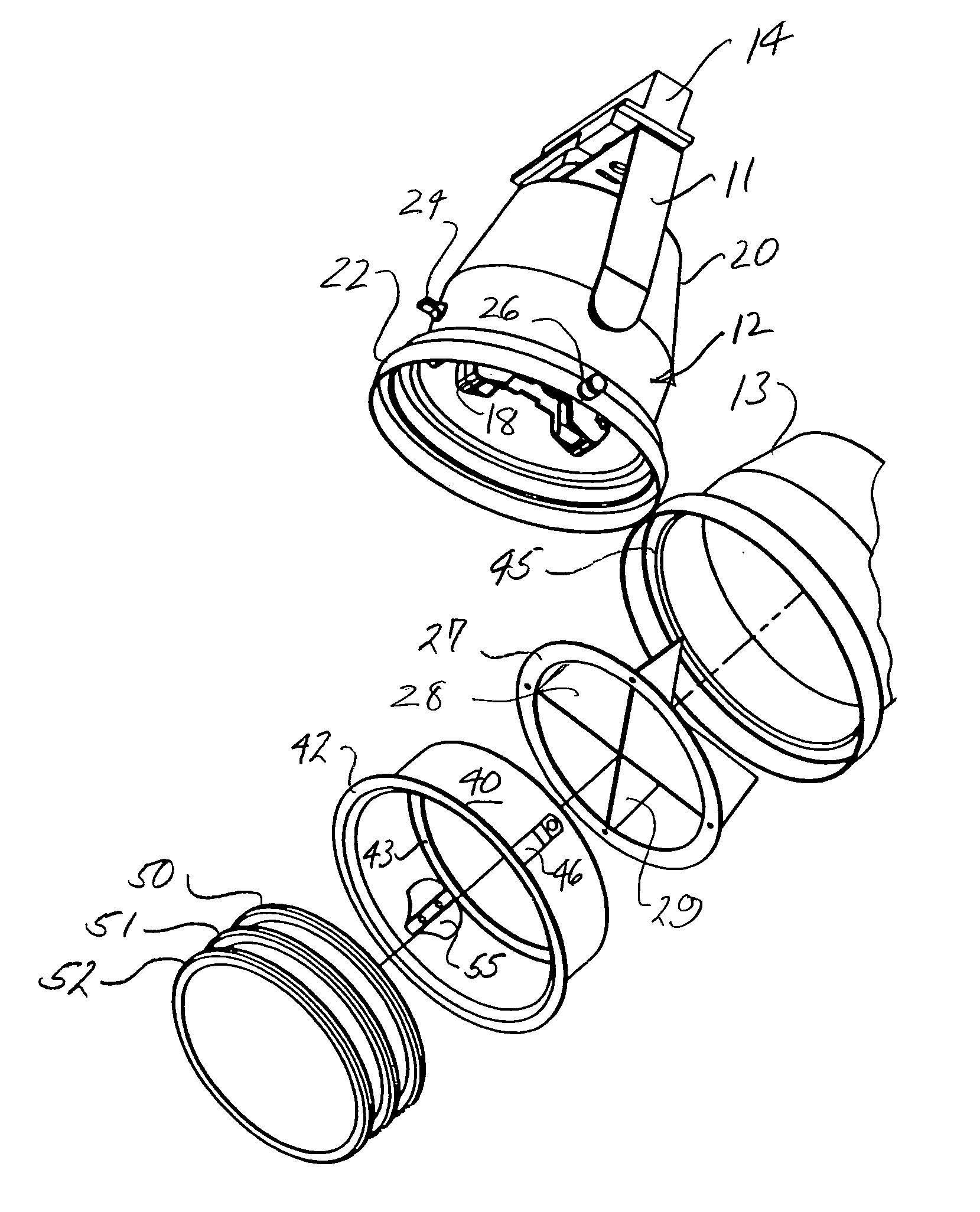
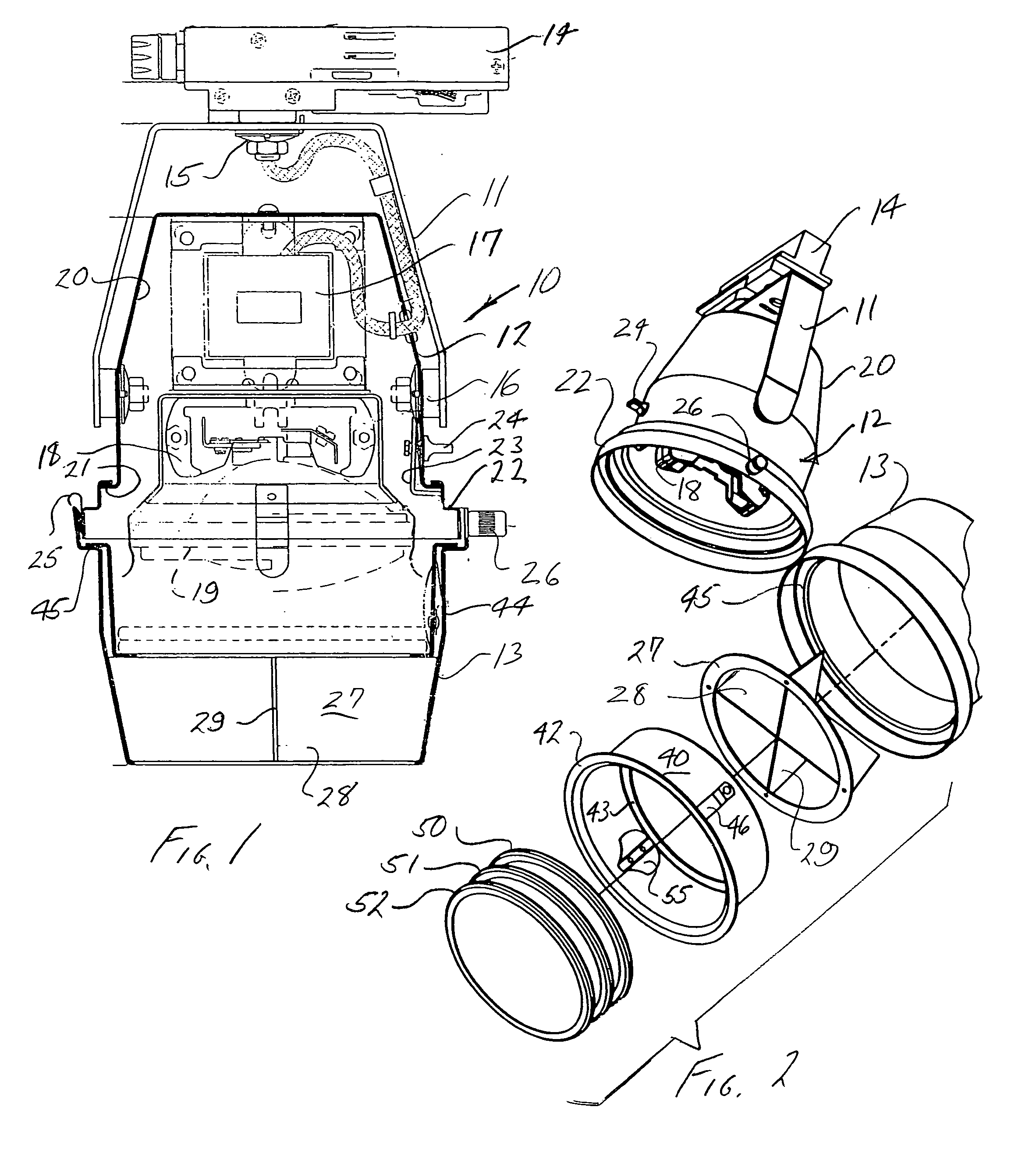
[0003]The present invention is directed to a specialized lighting fixture useful in theatrical lighting and other specialized applications, both commercial and residential, involving the use of accessory elements which are expected to be changed from time to time for achieving various lighting effects. Pursuant to the invention, a special accessory cartridge is provided, which is removably installed within the lighting fixture, in the outlet portion thereof, and incorporates facilities for expeditiously securing one or a plurality of disc-like accessory elements, for achieving desired lighting effects. The basic arrangement is such that the accessory cartridge can be loaded with one or more accessory elements, as desired for the effects to be achieved, and the pre-loaded accessory cartridge simply inserted into the lighting fixture. The installation and / or removal of the accessory cartridge is quickly and easily accomplished in a manner that minimizes the hazard to a workman on a ladder, where such is required in order to reach the lighting fixture.

Problems solved by technology

Additionally, since the foregoing operations frequently have to be attended to by a workman standing on a ladder, there are safety issues involved in connection with the installation, removal and / or exchange of accessory elements, which can be dealt with beneficially by simplifying and expediting the tasks involved.

Method used


Image

  • Accessory cartridge for lighting fixture
  • Accessory cartridge for lighting fixture
  • Accessory cartridge for lighting fixture

Examples


Embodiment Construction

[0017]Referring now to the drawings, the reference numeral 10 designates generally a specialized lighting fixture including a mounting bracket 11, a main body 12 and front barrel portion 13. The mounting bracket 11 typically is secured to an elongated track (not shown) by way of a housing 14, which can be secured to the track in any position along its length, all pursuant to well known concepts. The mounting bracket 11 is pivotally mounted at 15 for rotation about a vertical axis, and the body 12 of the fixture is pivotally mounted at 16 for rotation about a horizontal axis.

[0018]In the illustrated fixture, the body 12 may house a transformer 17 (for low voltage lighting) and mounts a suitable socket 18 for receiving an illuminating bulb 19.

[0019]The outer housing 20 of the main body 12 is provided at its lower end with an outwardly extending annular flange 21 which supports an annular rotation ring 22. The ring 22 is freely rotatable relative to the body housing 20, but can be lock...


PUM


Abstract

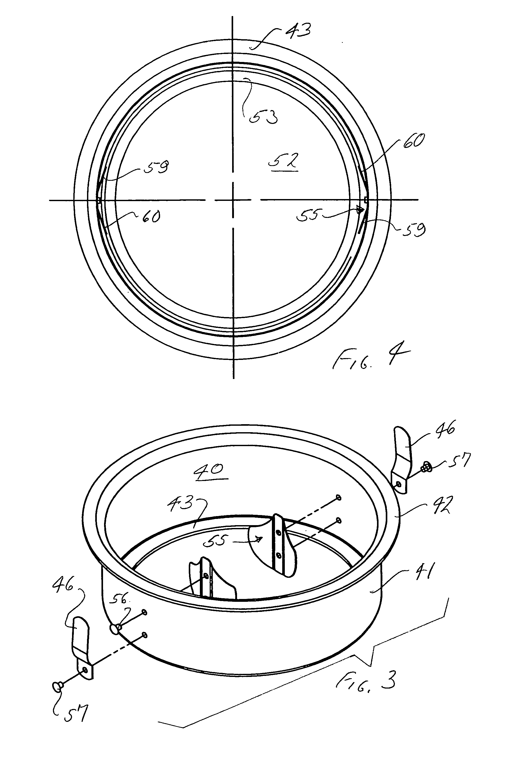
An accessory cartridge for removable reception in a specialized lighting fixture. A circular cartridge ring is provided with an internal lower flange, for supporting one or more flat, circular, disc-like accessory elements, such as filters. Retainer clips are positioned to engage at least the uppermost one of the disc-like accessory elements, such that one or more of the disc-like accessory elements may be easily installed within the cartridge ring and the entire series thereof automatically retained therein by engagement of at least the uppermost accessory element. The entire cartridge is designed to be bodily installed in or removed from the lighting fixture, to facilitate expeditious changing of accessory elements utilized with the lighting fixture. Preferentially, the lighting fixture is provided with a hingedly connected front barrel portion, which is constructed to receive and support the cartridge. The cartridge can be easily removed and / or installed when the barrel portion is hinged to an open position.

Description

BACKGROUND OF THE INVENTION[0001]Specialized lighting fixtures for such applications as theatrical lighting, museums, galleries, exhibits, etc. frequently involve the use of directed beam spotlight fixtures, typically mounted on a track, which can easily be adjusted as to location and as to direction of the beam for achieving desired results. In many cases, such specialized lighting fixtures employ accessory elements, such as color filters, conditioners, beam spreading lenses, etc.[0002]In environments in which the lighting requirements change from time to time, for example, in theaters, museums, etc., it may be necessary to replace or exchange some or all of the accessory elements installed in a particular fixture. The present invention is directed to mechanisms for significantly expediting and simplifying the installation, removal and / or exchange of accessory elements in specialized lighting fixtures of the type described. Additionally, since the foregoing operations frequently ha...

Claims


Application Information

Patent Timeline
Patent Type & Authority Patents(United States)
IPC IPC(8): F21S13/12F21S13/00F21S13/02
CPCF21V17/162F21V21/30F21V17/002F21V9/08F21W2131/406
Inventor KANE, KENNETH M.GENNARELLI, VINCENT D.
Owner LIGHTING SERVICES
Learn More