Drive system for mobile robot arm

a technology of driving system and robot arm, which is applied in the direction of coupling, interlocking clutch, sliding coupling, etc., can solve the problems of manual extension or collapse of the arm(s) by back-driving the motor, large force required to achieve the effect of lowering friction, quick and easy manipulation of the arms, and quick and easy completion

Active Publication Date: 2014-07-15
FOSTER-MILLER
View PDF8 Cites 8 Cited by
  • Summary
  • Abstract
  • Description
  • Claims
  • Application Information

AI Technical Summary

Benefits of technology

[0004]It is a further object of this invention to provide such an improved drive system which enables direct drive of the arm(s) but quick and easy manipulation of the arms in a manual collapse or extension mode.
[0005]It is a further object of this invention to provide such an improved drive system which employs a clutch system which can be adjusted between a high friction positive locked condition and a lower friction slip mode wherein arm collapse and extension can be quickly and easily accomplished.
[0006]It is a further object of this invention to provide such an improved drive system which the slip mode can be set to a lower friction range where the arm(s) can be re-positioned to hold its own weight in any new position without total collapse.
[0007]It is a further object of this invention to provide such an improved drive system where the friction can vary relatively smoothly between positive lock and slip modes.
[0011]In preferred embodiment there may be lower and upper articulated arms and there may be a lower drive system associated with the lower arm and an upper drive system associated with the upper arm. The clutch system may include a housing drivable by the drive motor, a stack of friction disks moveable with the housing and a plurality of clutch plates, interstitial of the friction discs and movable relative to the housing, an output shaft engaged and rotatable with the clutch plates, a pressure plate, a spider mechanism for urging the pressure plate to compress the friction disks and clutch plates together against the housing, a cover for constraining the friction disks, clutch plate, pressure plate and spider mechanism in the housing and an activator device for moving the spider mechanism between the locked and slip positions. The clutch system may further include a resilient spring member in the housing with the stack. The resilient spring member may be at the end of the stack in the housing. The resilient spring member may include elastomeric material. The spider member may include a plurality of fingers pivotably attached to a hub. The hub may be rotatable to radially extend and withdraw the fingers between locked and slip positions. The pressure plate may include a plurality of radial grooves corresponding to the fingers. The at least one of the grooves and fingers may be tapered to enable rotation of the hub to drive the fingers radially in and out to decrease and increase the force exerted by the pressure plate on the stack of friction discs and clutch plates. There may be a release mechanism for rotating the hub. The lower arm drive system may be fixed to and rotate the lower arm. The lower arm may house a chain drive for driving the upper arm and the chain drive may be driven by the upper arm drive system. There may be a second adjustable clutch mechanism and a second drive motor, each clutch system including an interlocking mechanism for mating with receptive interlocking mechanisms on the arm for tool free engagement of the arm between the clutch mechanisms. In the reduced friction slip position, the adjustable clutch system may support the arm's own weight.

Problems solved by technology

But in larger more powerful mobile robots the force required to manually extend or collapse the arm(s) by back-driving the motors is quite large and so may not be done as quickly as needed and may require more than average strength.

Method used


Image

  • Drive system for mobile robot arm
  • Drive system for mobile robot arm
  • Drive system for mobile robot arm

Examples


Embodiment Construction

[0024]Aside from the preferred embodiment or embodiments disclosed below, this invention is capable of other embodiments and of being practiced or being carried out in various ways. Thus, it is to be understood that the invention is not limited in its application to the details of construction and the arrangements of components set forth in the following description or illustrated in the drawings. If only one embodiment is described herein, the claims hereof are not to be limited to that embodiment. Moreover, the claims hereof are not to be read restrictively unless there is clear and convincing evidence manifesting a certain exclusion, restriction, or disclaimer.

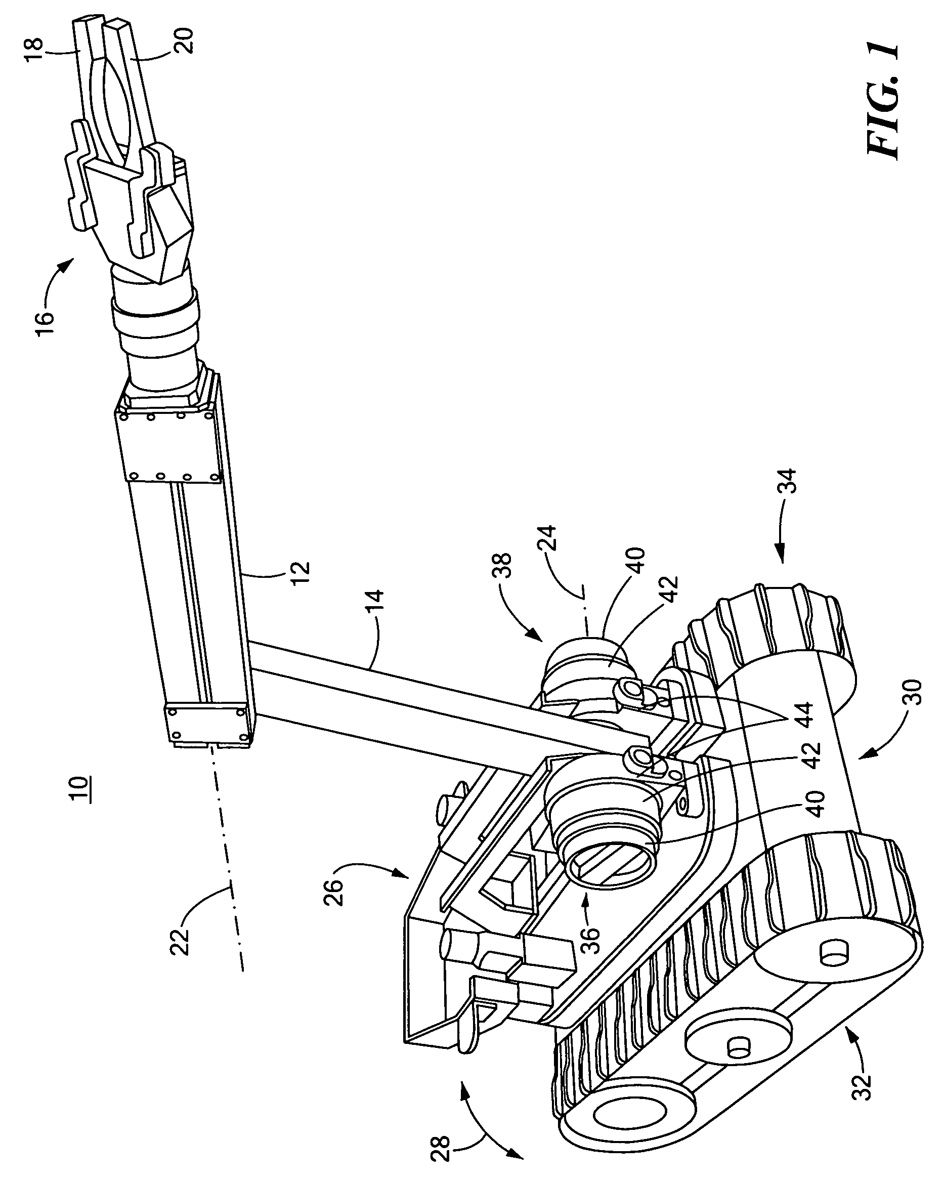
[0025]There is shown in FIG. 1 a mobile robot 10 having a pair of articulated arms, upper arm 12, and lower arm 14. Upper arm 12 has an end effector 16 which, for example, includes a pair of jaws or grippers 18 and 20. Upper arm 12 rotates on axis 22 with respect to lower arm 14. Lower arm 14 rotates on axis 24 with respect...


PUM


Abstract

A drive system for each arm of a mobile robot, each drive system including a drive motor and an adjustable clutch system interconnected between its associated arm and the drive motor and having a high friction locked position for enabling direct drive of the arm by the drive motor and a reduced friction slip position for enabling manual movement of the associated arm without back-driving the drive motor.

Description

FIELD OF THE INVENTION[0001]This invention relates to a drive system for mobile robot arms including an adjustable clutch system.BACKGROUND OF THE INVENTION[0002]Mobile, remotely controlled robots are becoming increasingly popular for use by the military, SWAT units, and police and fire departments. They typically can include an arm with an end effecter, several cameras, several antennas, and a deployable mast. Frequently the end effector is a gripper, e.g. a pair of jaws that can be opened and closed on command to grasp objects such as debris, hazardous material, unexploded ordinance and the like. The larger robots even have the capability to grip an injured, downed, person by some personal paraphernalia such as a shirt collar and drag them out of harm's way to safety. Often these end effectors, cameras, tools and other devices may be mounted on an arm, typically articulated, with two or more arms, an upper arm and a lower arm, for example. In emergency or combat situations it is o...

Claims


Application Information

Patent Timeline
Patent Type & Authority Patents(United States)
IPC IPC(8): F16D13/42F16D23/12
CPCF16D7/048B25J5/005F16D13/52F16D13/70F16D43/208
Inventor LANSBERRY, GEOFFREY B.ANDRUS, LANCE L.DESTEFANO, BRIAN
Owner FOSTER-MILLER
Why Eureka
Try Eureka