Collapsible siderail assembly

a siderail and assembly technology, applied in the field of siderail assembly, can solve the problems of affecting the close access and the surface is simply not enough, and achieve the effect of convenient cleaning

Active Publication Date: 2005-10-04
STRYKER CORP
View PDF15 Cites 67 Cited by
  • Summary
  • Abstract
  • Description
  • Claims
  • Application Information

AI Technical Summary

Problems solved by technology

For example, hospital beds located within hospital rooms were ordinarily constructed so as to remain in the room and not be capable of easy transport to and from the room.
Simply collapsing the siderail from its initial deployed position wherein the handrail thereon is above a plane of the patient supporting surface to a position below the plane of the patient supporting surface is simply not enough.
The siderail configuration will interfere with the close access required for the healthcare personnel to access the patient supported on the patient supporting surface.

Method used


Image

  • Collapsible siderail assembly
  • Collapsible siderail assembly
  • Collapsible siderail assembly

Examples


Embodiment Construction

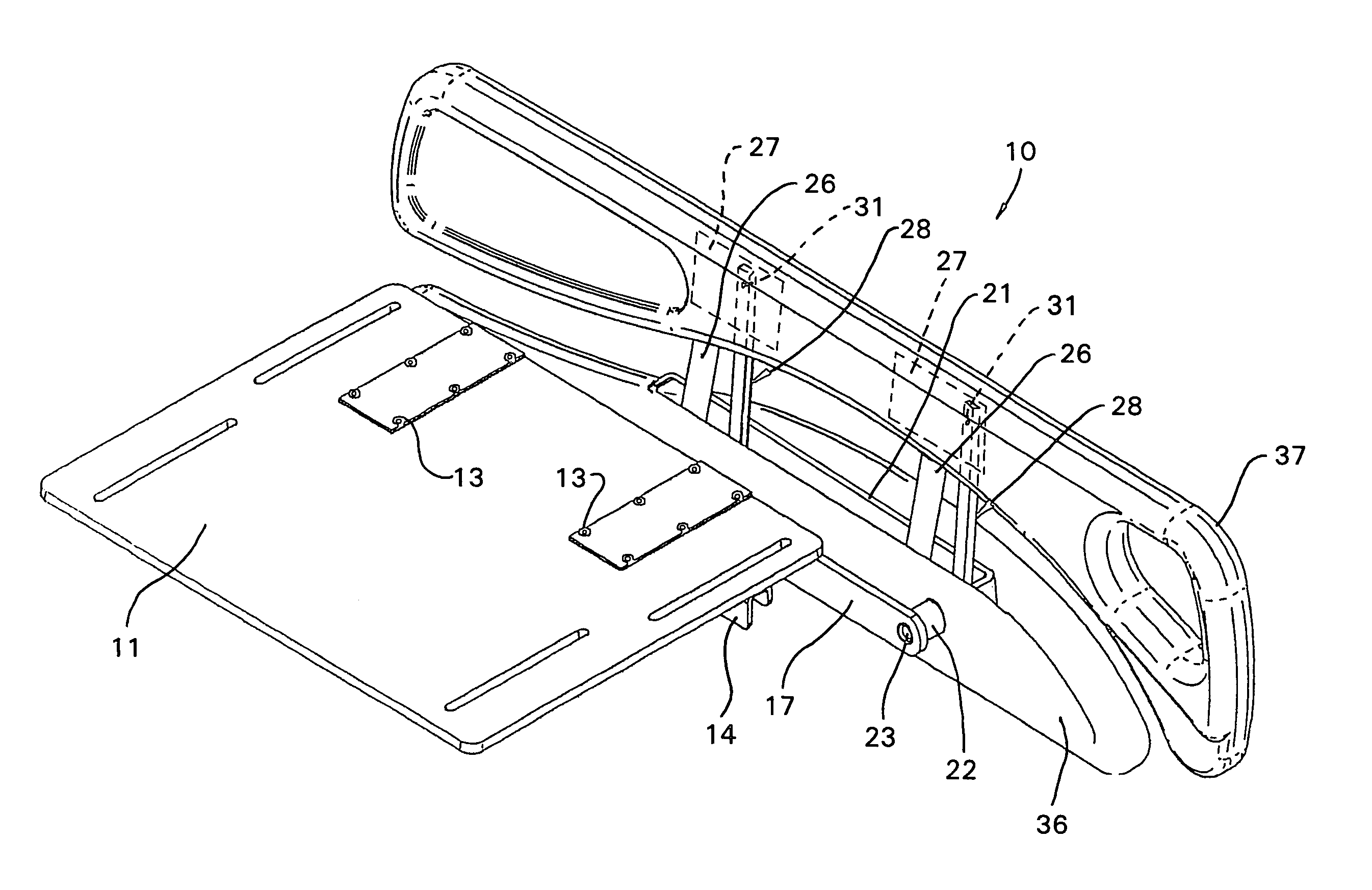
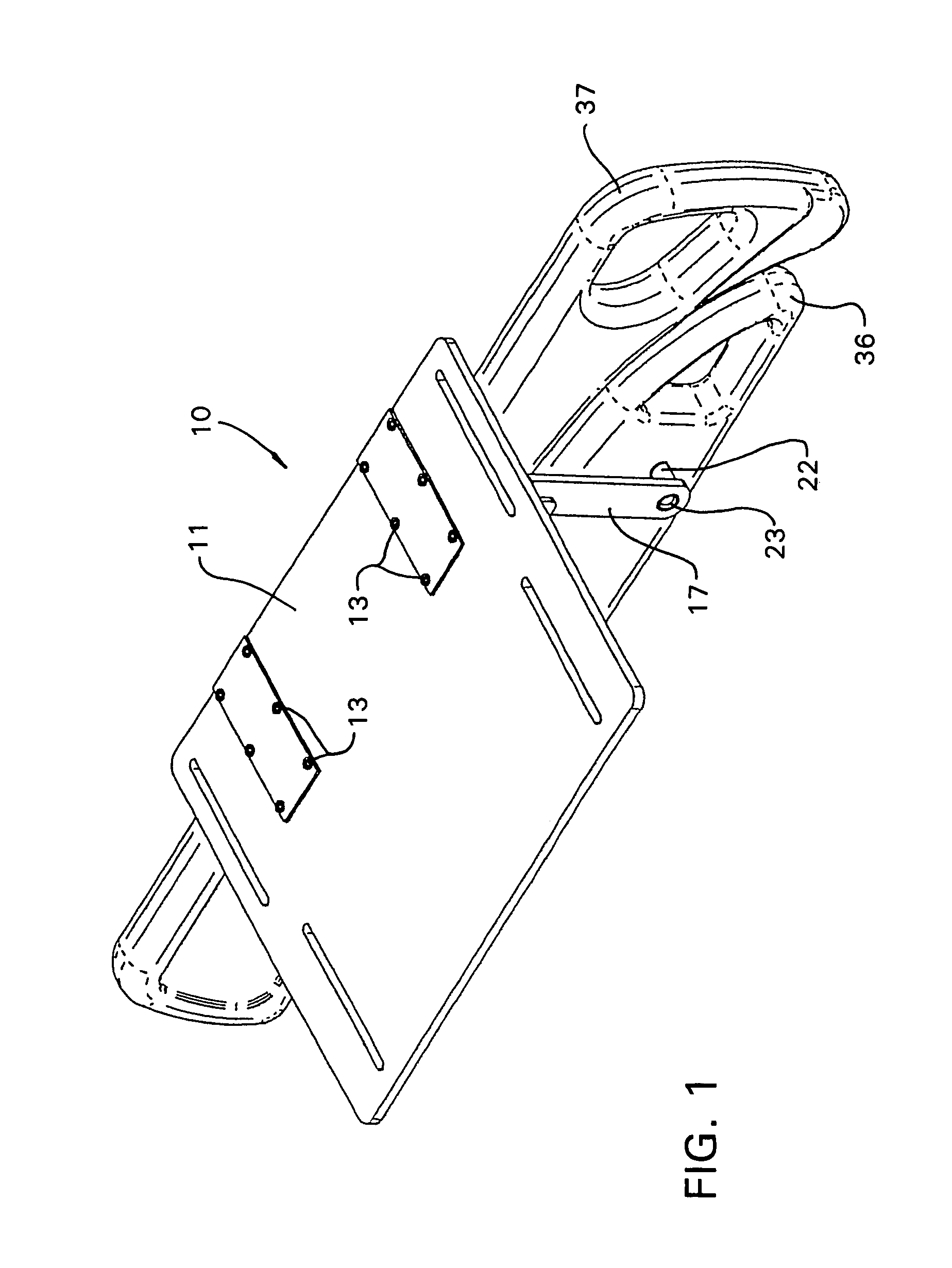
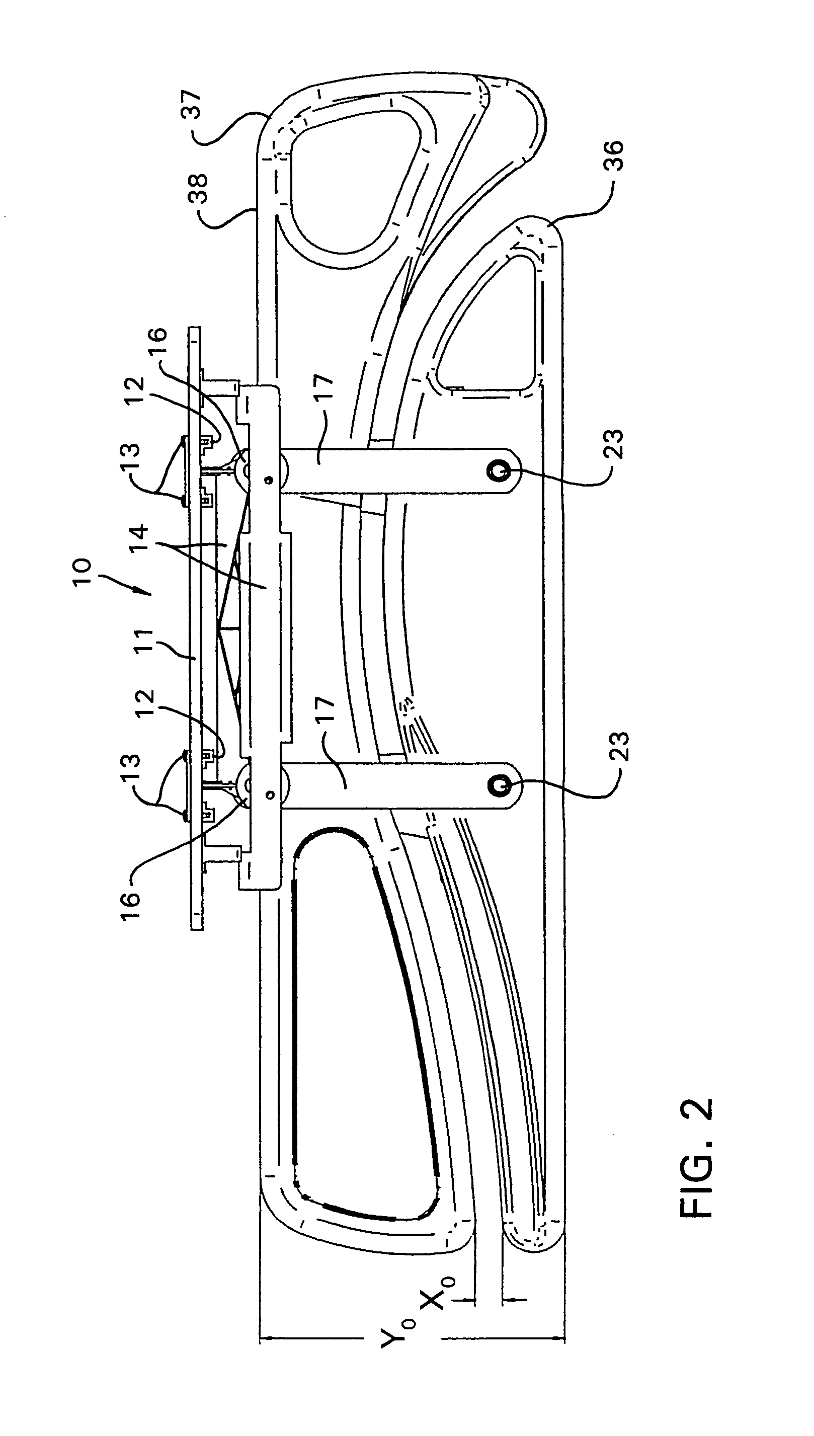
[0034]Certain terminology will be used in the following description for convenience in reference only and will not be limiting. The words “up”, “down”, “right” and “left” will designate directions in the drawings to which reference is made. The words “in” and “out” will refer to directions toward and away from, respectively, the geometric center of the device and designated parts thereof. Such terminology will include derivatives and words of similar import.

[0035]The invention disclosed herein will be usable on a variety of patient support apparatuses, namely, beds. Thus, a specific bed is not illustrated. However, one typical type of patient support apparatus and a siderail configuration therefor is disclosed in U.S. Pat. No. 6,360,385 presently commonly owned by the Assignee of record for this invention. The subject matter of U.S. Pat. No. 6,360,385 is to be incorporated herein by reference.

[0036]FIG. 1 illustrates a siderail assembly 10 embodying the invention. The siderail assem...


PUM


Abstract

A siderail assembly for a bed which includes a frame having thereon at least one pivotally supported arm for movement between first and second positions, the arm having at a distal end thereof a first connection location. A siderail support frame is pivotally connected to the distal end of the arm and has thereon at least one upstanding and elongate guide member. A siderail carriage frame is supported for movement along a length of the guide member toward and away from the siderail support frame and has thereon at least one second connection location. An elongate link is pivotally connected to and extends between the first and second connection locations to effect movement of the siderail carriage frame along the guide member toward and away from the siderail support frame in response to a pivotal movement of the arm relative to the frame to change the spacing between the siderail carriage frame and the siderail support frame.

Description

FIELD OF THE INVENTION[0001]This invention relates to a siderail assembly for a bed and, more particularly, to a siderail assembly that is configured to expand in the top to bottom dimension thereof as the siderail transitions from a stowed position to a fully deployed position.BACKGROUND OF THE INVENTION[0002]Equipment for use in a patient care facility has been categorized in the past into constructions adapted for limited use. For example, hospital beds located within hospital rooms were ordinarily constructed so as to remain in the room and not be capable of easy transport to and from the room. As a result, it became necessary to transfer the patient from the hospital bed to a patient transport carrier for transporting the patient to a remote location for additional treatment, whereat the patient would likely need to be transferred to an additional supporting surface. It would be desirable to provide a patient supporting surface, namely, a hospital bed, that is usable both in th...

Claims


Application Information

Patent Timeline
Patent Type & Authority Patents(United States)
IPC IPC(8): A47D7/00A47C21/00A47C21/08A61G7/00
CPCA61G7/0507A61G2007/0509A61G7/0509
Inventor LEMIRE, GUY
Owner STRYKER CORP
Why Eureka
Try Eureka