Method for extracting an illuminate zone from a photosensor matrix

Active Publication Date: 2005-10-11
MBDA FRANCE
View PDF8 Cites 5 Cited by
  • Summary
  • Abstract
  • Description
  • Claims
  • Application Information

AI Technical Summary

Benefits of technology

[0015]in forming search zones of ever decreasing size, convergence onto the illuminated zone of said matrix occurs very quickly.
[0016]Thus,

Problems solved by technology

A major drawback concerning the use of such a light-detecting device for guiding a missile lies in the difficulty and in the considerable duration needed to extract the zone which is illuminated by the laser pulse from said matrix of photosensors, and to locate this zone on the matrix, so as to obtain information concerning the position of the target, which information is necessary for guiding the missile.
Such an analysis, if it is imple

Method used


Image

  • Method for extracting an illuminate zone from a photosensor matrix
  • Method for extracting an illuminate zone from a photosensor matrix
  • Method for extracting an illuminate zone from a photosensor matrix

Examples


Embodiment Construction

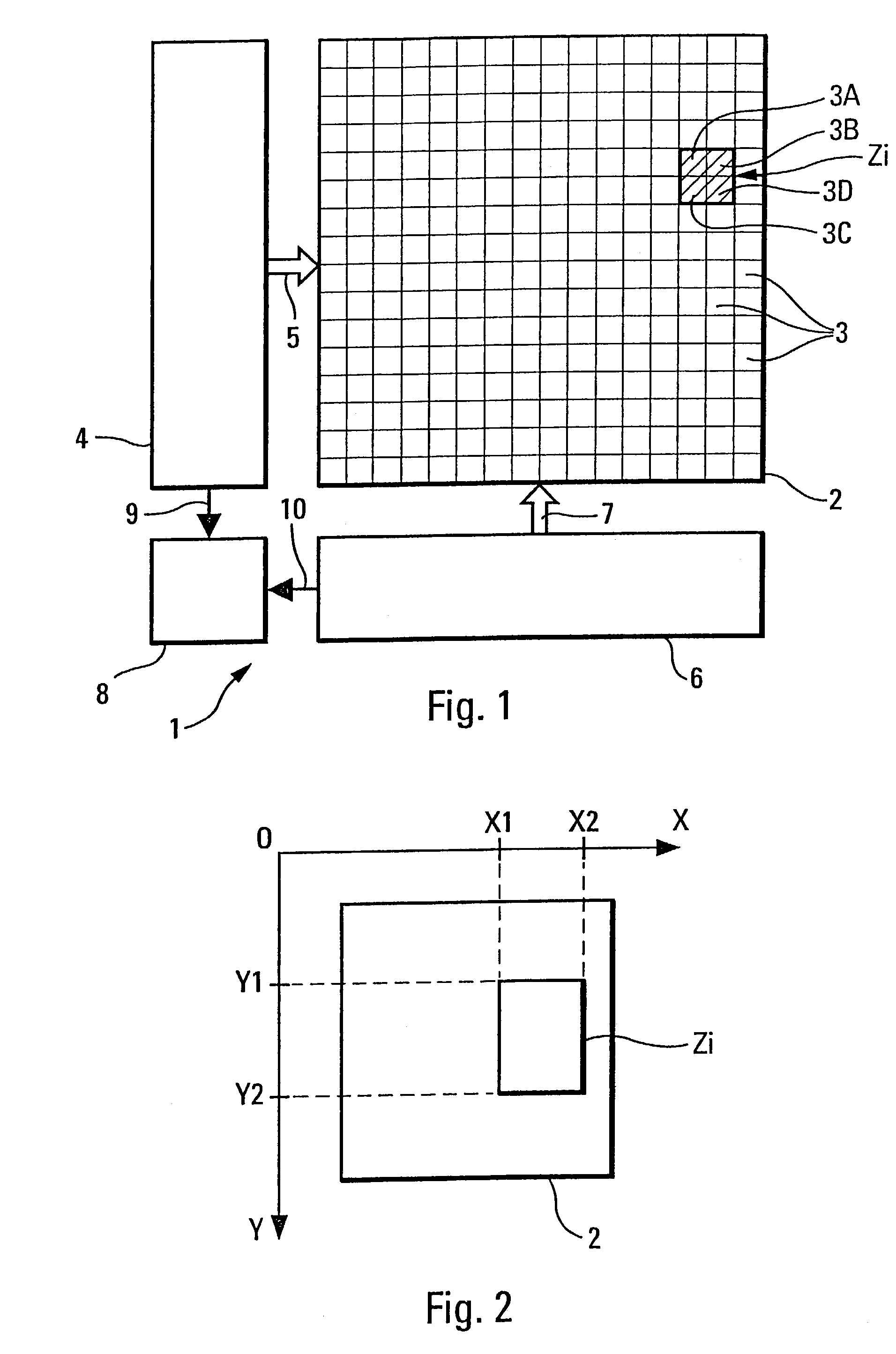
[0030]The device 1 according to the invention and shown schematically in FIG. 1 is designed to detect a light signal, in particular a laser pulse.

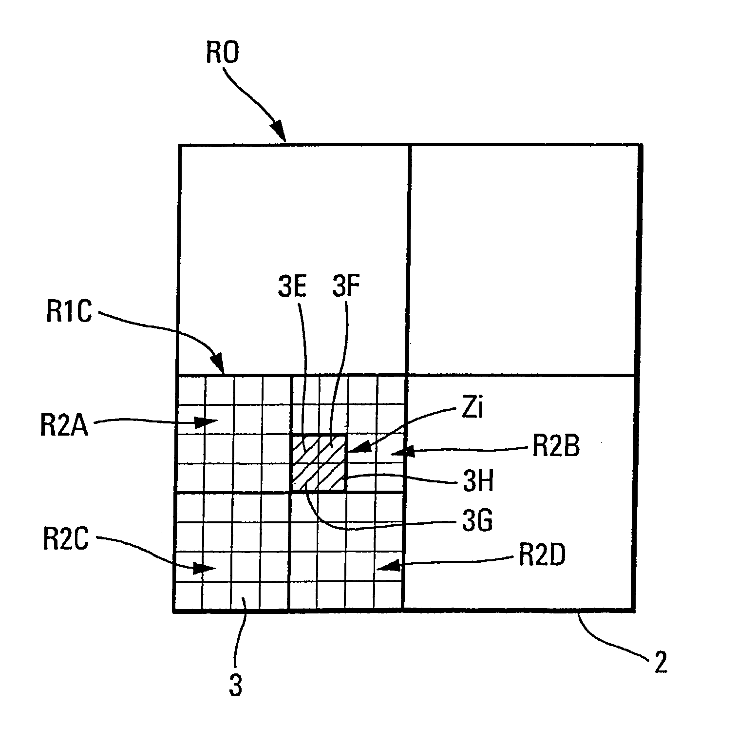
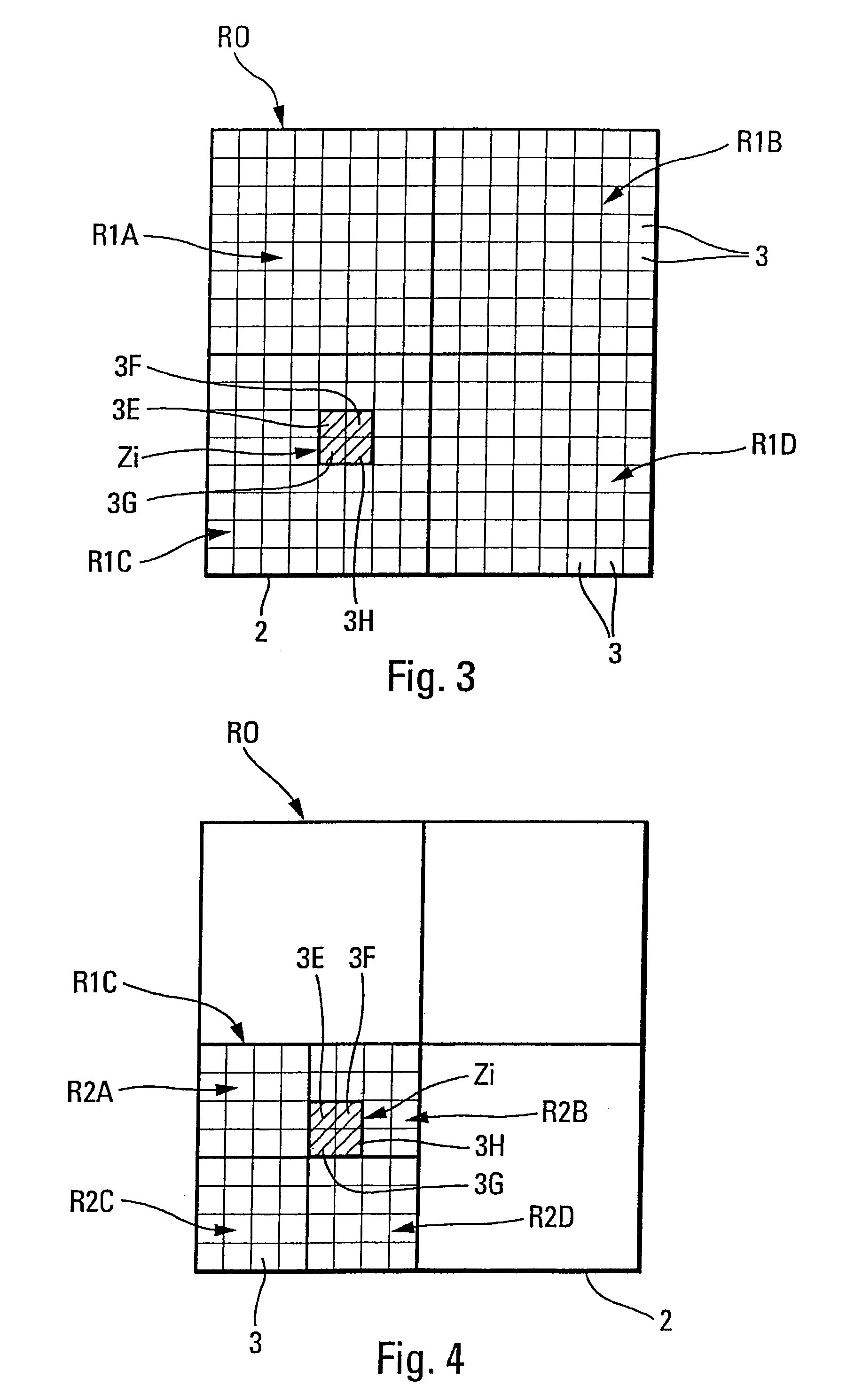
[0031]Said device 1 is of the type comprising a matrix 2 of photosensors 3 which are arranged in rows and in columns and which are each able to take one of two states, an active state when they are illuminated and therefore activated, and a passive state when they are not illuminated and therefore not activated. This matrix 2 is illuminated by a light ray on an illuminated zone Zi corresponding to the formed set of sensors 3A, 3B, 3C, 3D which are therefore activated.

[0032]According to the invention, said light-detecting device 1 further comprises a cell for selecting rows 4 which is connected via a row bus transmission link 5 to the matrix 2 and a cell for selecting columns 6 which is connected via a column bus transmission link 7 to said matrix 2, said cells 4 and 6 being able to extract said illuminated zone Zi from the matrix 2, by imp...


PUM


Abstract

A method for extracting an illuminated zone from a matrix of photosensors may include: (a) dividing the matrix into a plurality of search zones, (b) searching for the presence of an active photosensor in the search zones, (c) stopping the search as soon as an active photosensor is found in a search zone, and (d) further subdividing the first search zone determined to have an active photosensor into a plurality of search zones. Additionally the method may include repeating steps (b) through (d) until a search zone having only active photosensors is obtained.

Description

FIELD OF THE INVENTION[0001]The present invention relates to a method for extracting an illuminated zone from a matrix of photosensors of a light-detecting device, and a light-detecting device capable of implementing this method.BACKGROUND OF THE RELATED ART[0002]Such a light-detecting device, which normally comprises, as described for example in patent EP-0 633 457, a matrix of photosensors which are arranged in rows and in columns and which are each able to take one of two states, an active state when they are illuminated and an inactive state when they are not illuminated, is more particularly, although not exclusively, designed for detecting a very-short-duration laser pulse which is emitted in an ambient light environment of variable illumination, for example at a predetermined frequency.[0003]By way of illustration, the laser pulse to be detected may be emitted by a laser source which is aimed at a target, for example a tank, in order to highlight it, so that it can be located...

Claims


Application Information

Patent Timeline
IPC IPC(8): G01S3/784G01S3/78G06K9/32
CPCG01S3/784G06K9/3241F41G7/226F41G7/2293G06V10/255
Inventor BOUBAL, MICHELMICHELIS, JEANDUMAS, MICHEL
Owner MBDA FRANCE
Why Eureka
Try Eureka