Retailing display rack with adjustable display arm

Inactive Publication Date: 2005-11-01
ALPERSON JOEL
View PDF13 Cites 42 Cited by
  • Summary
  • Abstract
  • Description
  • Claims
  • Application Information

AI Technical Summary

Benefits of technology

[0007]The present invention provides an improved retailing display rack that is formed of a base member, a tubular housing member that extends upwardly from said base member and has an inner channel member that defines a pair of spaced apart chambers in said housing member for receiving a pair of display arm members. At least one side o

Problems solved by technology

Furthermore, the use of display racks having vertically separated display arms also are not new.
Nevertheless, such prior art display racks have been deficient in their construction in that they do not provide a reliable and relatively simple method for attachment and support of the display arms.

Method used


Image

  • Retailing display rack with adjustable display arm
  • Retailing display rack with adjustable display arm
  • Retailing display rack with adjustable display arm

Examples


Embodiment Construction

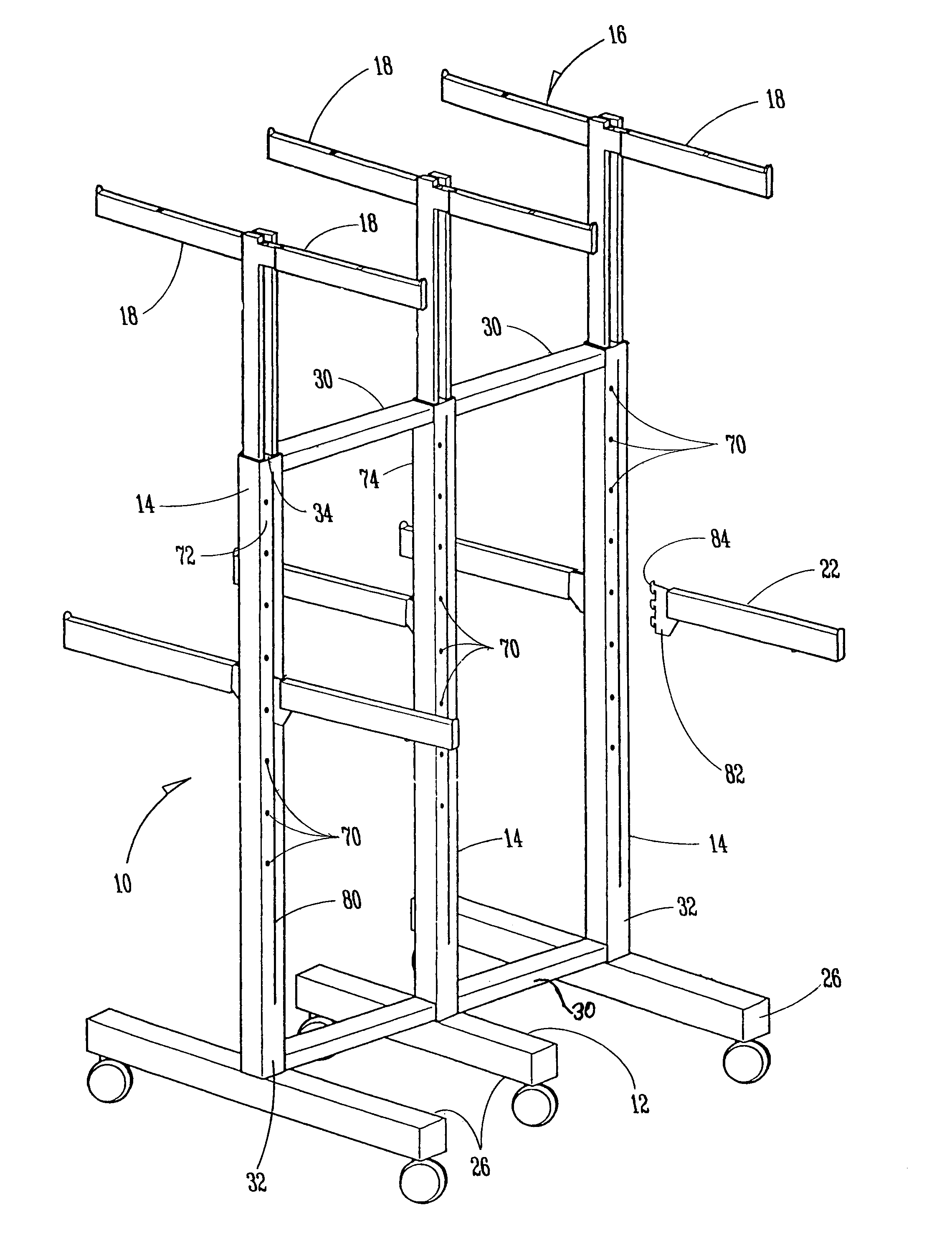
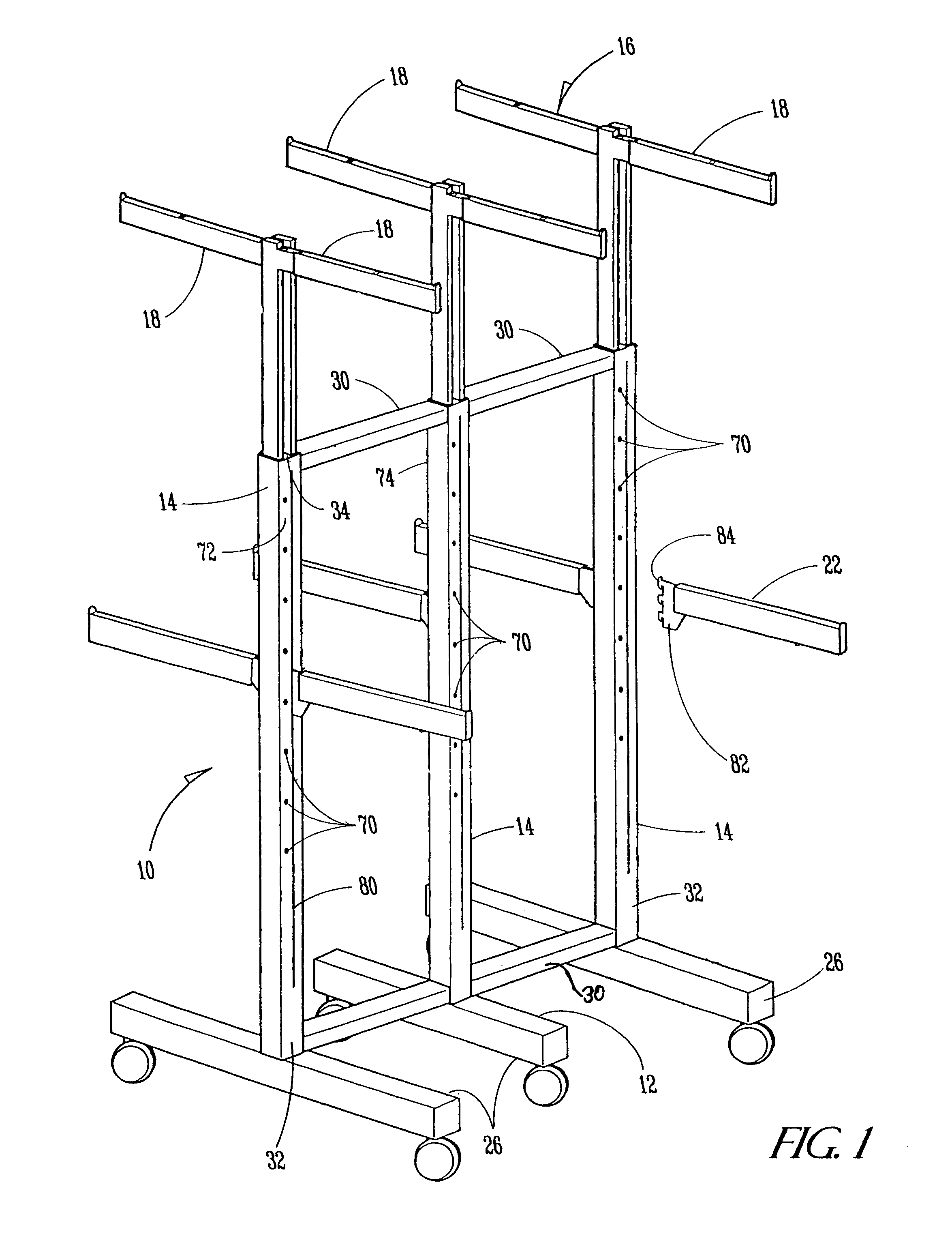
[0015]Referring now to the drawings and with reference first to FIG. 1 a preferred embodiment of the retailing display rack of the present invention is shown at 10, which rack is adapted to be utilized for the displaying of merchandise in a multi-level environment. The rack 10 includes a base 12, a plurality of tubular housing members 14 extending vertically upward from the base 12, a plurality of display support members 16 each having a horizontal upper arm 18 and a downwardly depending leg 20 (see FIG. 4) for positioning within an associated housing member 14 and a plurality of lower arms 22 that are removably attachable to the housing members 14, all as will be described below.

[0016]The base 12 includes three horizontally aligned and parallel base members 26 that are supported off the ground by associated casters 28 located at each end of the base members 26. The housing members 14 are connected together by spanning struts 30 that bridge between the housing members 14.

[0017]To fo...


PUM


Abstract

A retail display rack having vertically adjustable upper and lower display arms associated with a tubular housing structure that is vertically oriented for mounting the upper and lower arms thereon at selectable heights.

Description

RELATED U.S. APPLICATION DATA[0001]Provisional application No. 60 / 487,300, filed on Jul. 15, 2003.BACKGROUND OF THE INVENTION[0002]1. Field of the Invention[0003]The present invention relates in general to retailing display racks that typically are utilized for holding garments or other material for viewing by customers and more specifically relates to display racks having vertically adjustable upper and lower display arms.[0004]2. Description of the Prior Art[0005]A wide variety of retailing display racks are known in the prior art. Furthermore, the use of display racks having vertically separated display arms also are not new. Nevertheless, such prior art display racks have been deficient in their construction in that they do not provide a reliable and relatively simple method for attachment and support of the display arms.[0006]The present invention is designed to avoid the deficiencies of the prior art structures and provide a display rack with upper and lower display arms that ...

Claims


Application Information

Patent Timeline
IPC IPC(8): A47B43/00A47B53/00A47F5/13A47F7/19
CPCA47F5/137A47F7/19
Inventor ALPERSON, JOEL
Owner ALPERSON JOEL
Why Eureka
Try Eureka