
Wheelchair

Inactive Publication Date: 2005-11-22
SWANY
View PDF18 Cites 8 Cited by
  • Summary
  • Abstract
  • Description
  • Claims
  • Application Information

AI Technical Summary

Benefits of technology

[0008]The present invention was developed for the purpose of solving such drawbacks. An important object of the present invention is to provide a wheelchair which comfortably drives wheels so as to prevent the user's hand from hurting, and easily drives wheels allowing light griping without slip. Another important object of the present invention is to provide a wheelchair with a smaller wheel width, thereby achieving easy and smooth movement even in a small room. A further important object of the present invention is to provide a wheelchair which has simple structure, which is good for mass production with lower costs.

Problems solved by technology

But the users hand can hit the arm causing pain and discomfort.
It is impossible to drive the wheel by keeping his hand on or around the metal ring.
Further, if a user grips protruding portion 42 hard to prevent slipping, then his hand gets fatigued easily.
This configuration causes a wider size of the whole wheel, and it would be difficult to move in a small room smoothly because of the wide side.
Also, another wheelchair in the related art having a wheel with a metal ring has similar drawbacks, i.e., its metal ring protrudes outwardly, thereby resulting in a wider size of the wheel.
Also, it would be difficult to smoothly move in the small room.

Method used


Image

  • Wheelchair
  • Wheelchair
  • Wheelchair

Examples


Embodiment Construction

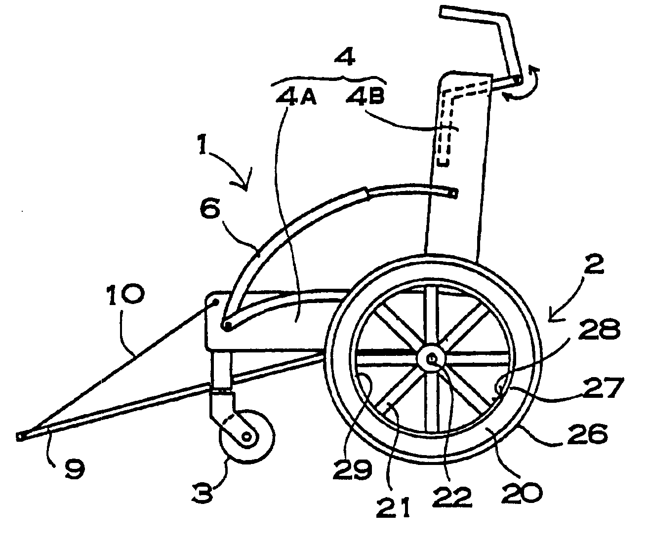
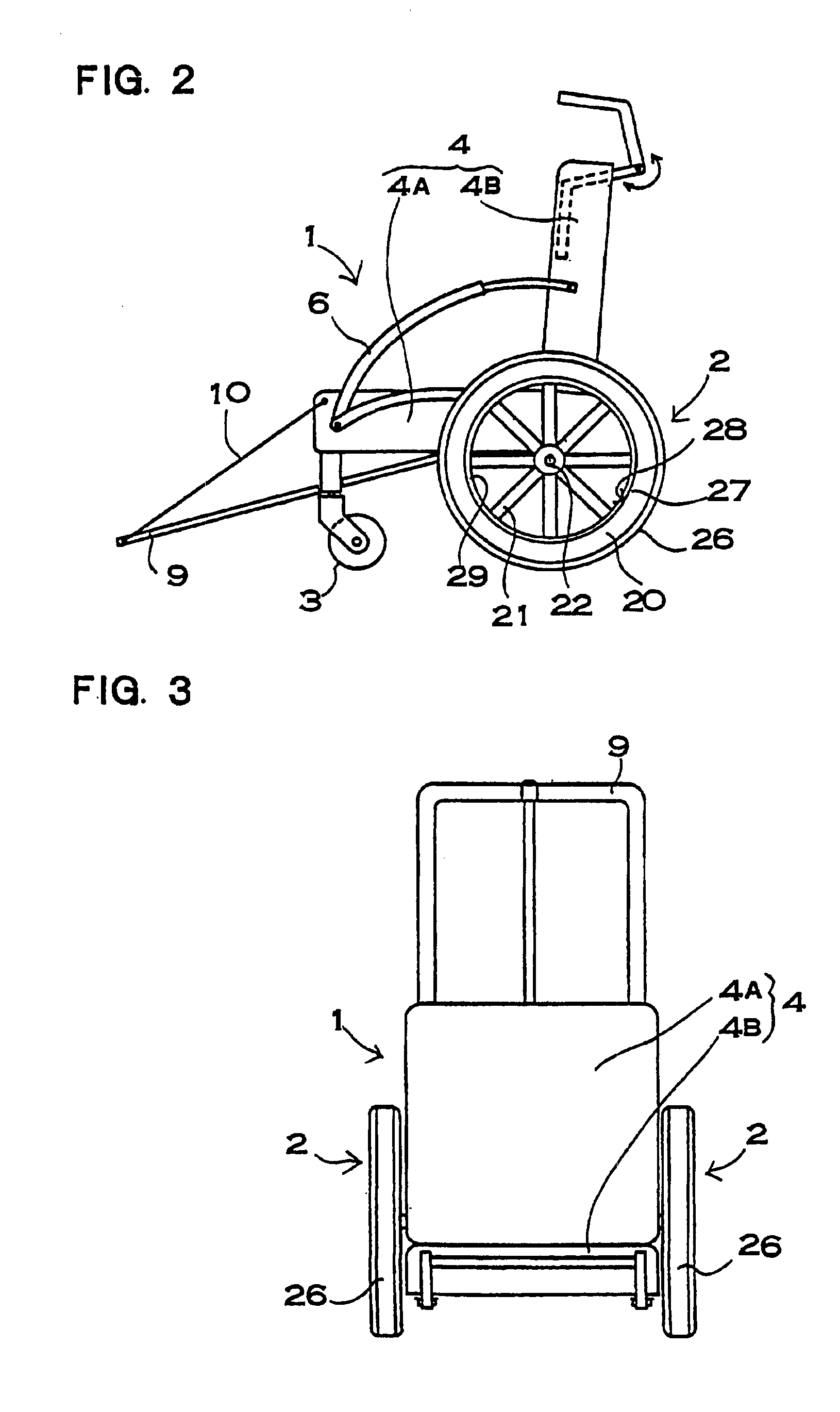
[0043]A wheelchair shown in FIG. 2 to FIG. 4 comprises a chair part 1 on which a user can sit, wheels 2 rotatably attached to the both sides of the chair part 1, and free wheels 3 which are positioned in the front portion of the chair part 1 and are able to change the direction of travel of the wheelchair. The wheelchair, as illustrated in FIG. 5, is configured to be folded and housed in bag case 4 to easily carry the wheelchair. It should be noted that the present invention is directed to the whole mechanism of the wheelchair, thus the construction of the whole wheelchair is not limited to those shown in FIGS. The invention can employ any construction such as currently used or future developed structure, for example, a non-foldable wheelchair, or a wheelchair foldable in width only.

[0044]The wheelchair shown in FIGS. 2-4 employs the chair part 1 as the bag case 4. The bag case 4 comprises a first bag case part 4A serving as a seat base and a second bag case part 4B serving as a bac...


PUM


Abstract

A wheel including a rim member (20), and a hub member (22) which is connected to a center of the rim member via a wheel part (21). The wheel is rotatably connected to a chair part (1). The wheel fixes a cushion ring 26 on the outer periphery of the rim member (20), and has a continuous wall portion (31) on an outside portion of the outer periphery. The continuous wall portion (31) is shaped in form of a ring along the rim member (20), and provides a grip ring (27) on an edge portion thereof. The wheel provides a finger-holding cavity (32) which is formed by the continuous wall portion (31).

Description

BACKGROUND OF THE INVENTION[0001]1. Field of the Invention[0002]The present invention relates to a wheelchair with a chair part and wheels provided on both sides of the chair part, allowing a user who sits on the chair to move himself by rotating the wheels using his own hands.[0003]2. Description of the Related Art[0004]A current used wheelchair has a wheel which fixes a hub via spokes on a rim fixing a tire around thereon, and a metal ring is fixed on the outer side of the rim. The metal ring has a smaller diameter than the tire, and is spaced apart from the rim to permit it to be easily grasped to drive the wheel. To separate the metal ring from the rim, the metal ring is fixed by arm located in a predetermined space in order to fix the rim.[0005]In use of the wheelchair having this construction, a user grasps the metal ring and rotates the wheel. But the users hand can hit the arm causing pain and discomfort. To prevent his hand from hitting the arm while driving the wheel, it i...

Claims


Application Information

Patent Timeline
IPC IPC(8): A61G5/00A61G5/08A61G5/10A61G5/02A61G5/12
CPCA61G5/02A61G5/028A61G5/08A61G5/10A61G2005/0825A61G2005/0891A61G2005/125A61G2005/128A61G5/0825A61G5/0891A61G5/125A61G5/128
Inventor MIYOSHI, ETSUO
Owner SWANY
Learn More