Apparatus for distinguishing between tubing assemblies

Inactive Publication Date: 2005-11-22
SAINT GOBAIN PERFORMANCE PLASTICS CORP
View PDF18 Cites 14 Cited by
  • Summary
  • Abstract
  • Description
  • Claims
  • Application Information

AI Technical Summary

Problems solved by technology

However, in many situations, being able to see the contents of the tubing does not enable one to distinguish between the tubes.
Moreover, it may be necessary to distinguish between the tubes at a time when they are empty, such as during the assembly and set up of a particular arrangement of tubes and vessels, in which case being able to see through the tubes is unhelpful.
However, such adhesives generally have not been found to reliably bond to the materials commonly used to make stoppers and tubes.
Moreover, physically attached signs or labels can, overtime, become worn and illegible, or may eventually become detached from the appropriate stopper or tube.
Such labels may also be difficult to read from a plurality of different angles and may, depending on the environment in which the stopper and the tubes are used, become difficult to read due to debris that may build up on the labels.
This overmolding technique creates a raised section on the stopper or tubing and involves a additional manufacturing process, which generally results in additional manufacturing costs.

Method used


Image

  • Apparatus for distinguishing between tubing assemblies
  • Apparatus for distinguishing between tubing assemblies
  • Apparatus for distinguishing between tubing assemblies

Examples


Embodiment Construction

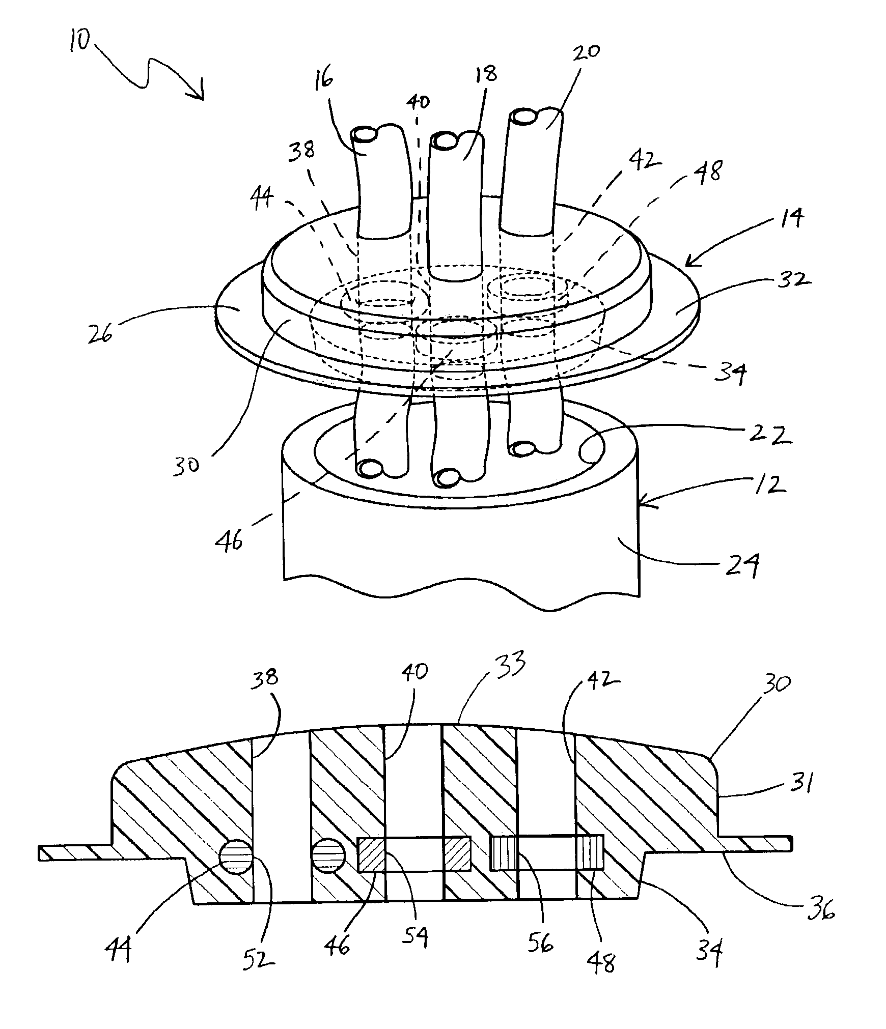
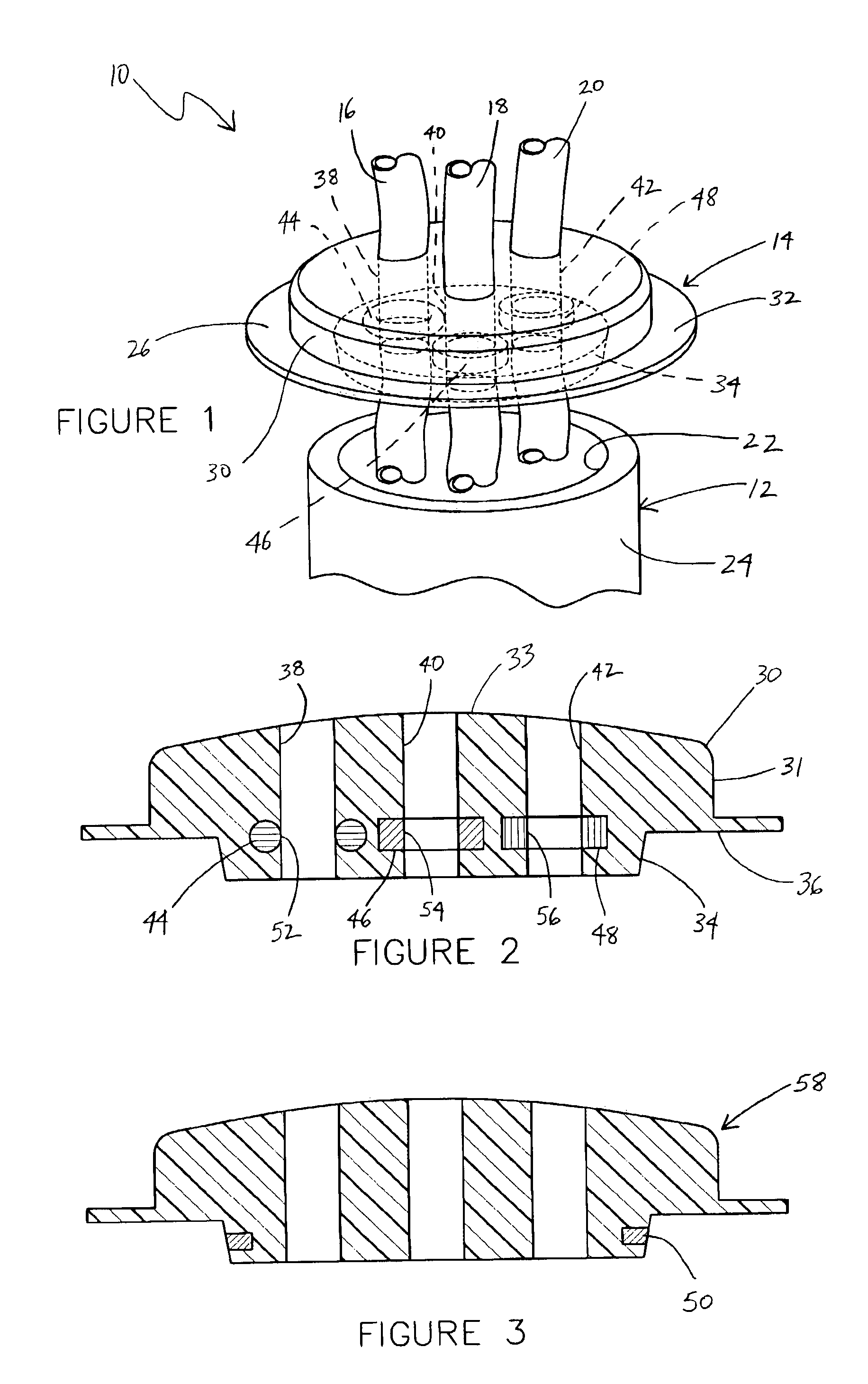
[0021]Referring to FIG. 1, a tubing system 10 is shown according to a preferred embodiment. Tubing system 10 includes a vessel 12, a stopper 14, and tubes 16, 18, and 20.

[0022]Vessel 12 may be any one of a variety of different containers, beakers, bottles, canisters, flasks, receptacles, tanks, vats, vials, etc. that are generally used to hold or contain substances or articles. Vessel 12 may be made from a number of different materials (such as a polymer, glass, wood, ceramic, etc.) and may take one of a plurality of different shapes and sizes. According to a preferred embodiment, vessel 12 is of a type used in the pharmaceutical industry and has an open first end 22, side wall(s) 24, and a closed bottom end (not shown). Open first end 22 is configured to receive stopper 14, which may be used to help retain or control the substance or matter within vessel 12.

[0023]Tubes 16, 18, and 20 are each silicone tubes that are used extensively in medical, pharmaceutical, chemical, and other a...


PUM


Abstract

An apparatus for use in identifying or distinguishing at least one substance or article associated with the apparatus is disclosed. The apparatus comprises a translucent body and an identification formation. The translucent body is for defining or engaging an opening. The identification formation is embedded in the translucent body in a predetermined relationship with the opening. At least one characteristic of the identification band is visible through the translucent body.

Description

FIELD OF THE INVENTION[0001]The present invention relates generally to the field of tubing assemblies. More particularly, the present invention relates to a structure or apparatus for distinguishing between different tubing assemblies.BACKGROUND OF THE INVENTION[0002]Stoppers are widely used to seal a vessel or to limit the ability of the contents to escape from the vessel. Some stoppers are solid and thereby prevent any of the matter from entering or leaving the container, while others may include one or more apertures that allow one or more tubes to be inserted into the container. When more than one tube is inserted through a stopper into a vessel, the tubes may be used for different functions or may carry different materials. For example, one tube may be used to insert a certain substance into the vessel, while another tube may be used to remove matter from the vessel or to insert another substance into the vessel. The tubes also may be inserted into the container at different de...

Claims


Application Information

Patent Timeline
IPC IPC(8): F16L35/00
CPCF16L35/00
Inventor MASTROPAOLO, JEFFREY A.
Owner SAINT GOBAIN PERFORMANCE PLASTICS CORP
Why Eureka
Try Eureka