Check patentability & draft patents in minutes with Patsnap Eureka AI!

Electric fire assembly

a technology of fire assembly and electric fire, which is applied in the direction of domestic stoves or ranges, instruments, heating types, etc., can solve the problems of high manufacturing cost and the inability to provide the flame effect wholly satisfactory

Inactive Publication Date: 2005-11-22
GHP GRP
View PDF63 Cites 22 Cited by
  • Summary
  • Abstract
  • Description
  • Claims
  • Application Information

AI Technical Summary

Benefits of technology

[0004]According to the present invention there is provided an electric fire assembly comprising an electric heater and a flame effect arrangement, the arrangement comprising a light source, a rotatable light pattern provider comprising a hollow member which has a partial opaque pattern on the exterior, and an at least a translucent screen, the arrangement being configured such that the light from the light source is provided in the interior of the pattern provider directly onto the rear of the screen, such that as the pattern provider is rotated a changing pattern of light can be seen on the front of the screen whereby to provide a flame effect.

Problems solved by technology

In general, these have thus been relatively bulky and many have included quite complex arrangements and have thus been quite expensive to manufacture.
Also the flame effect provided has often not always been wholly satisfactory.

Method used


Image

  • Electric fire assembly
  • Electric fire assembly
  • Electric fire assembly

Examples


Embodiment Construction

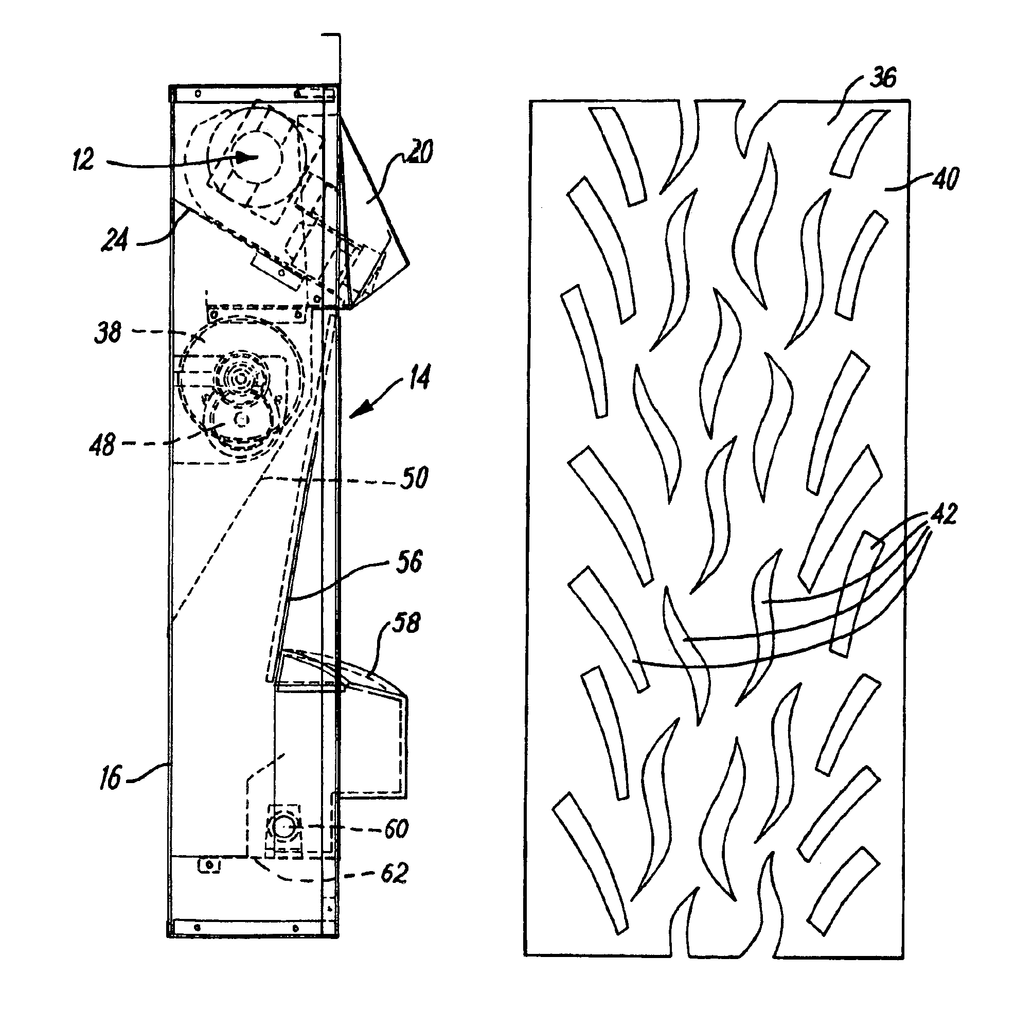
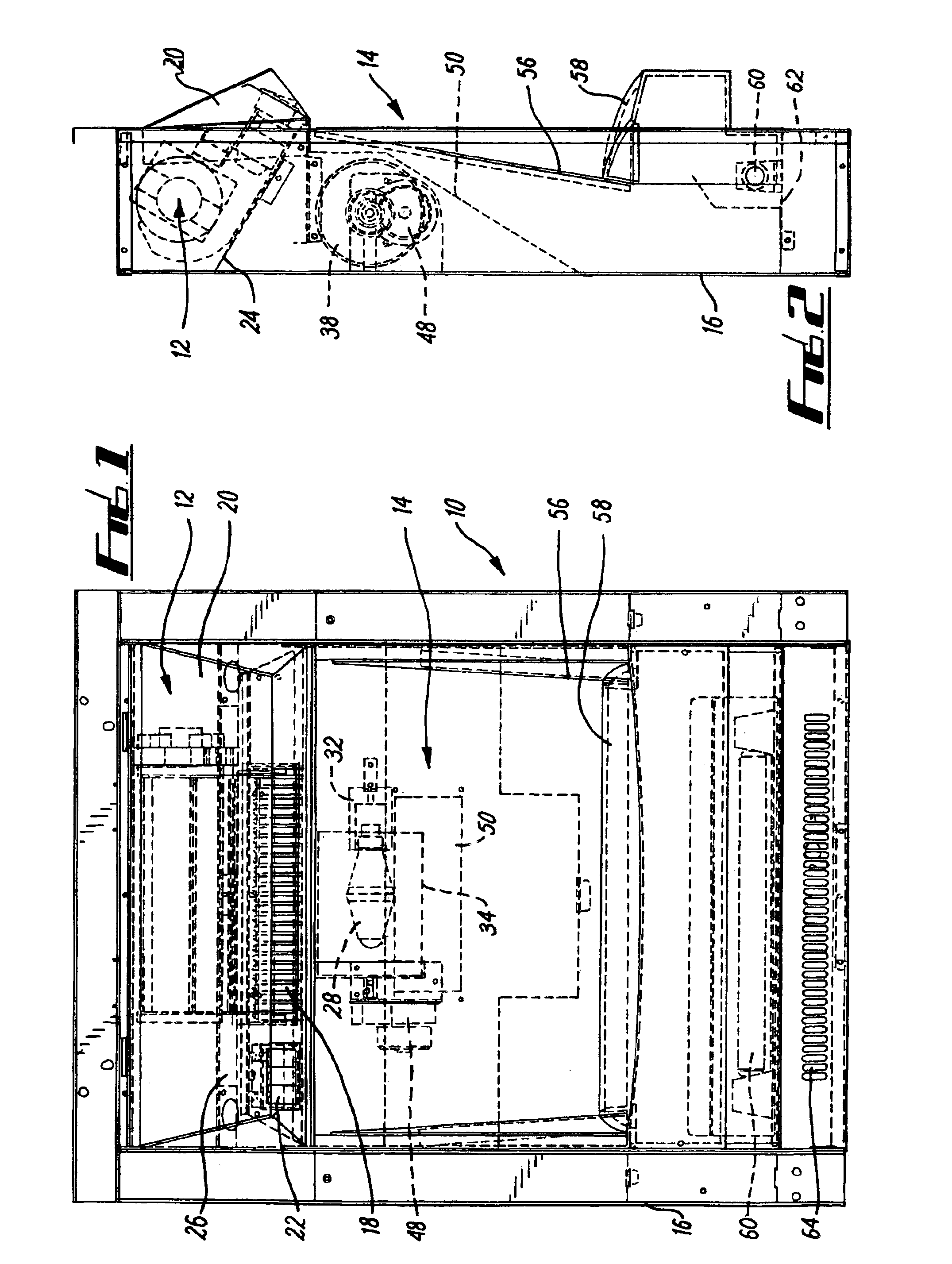
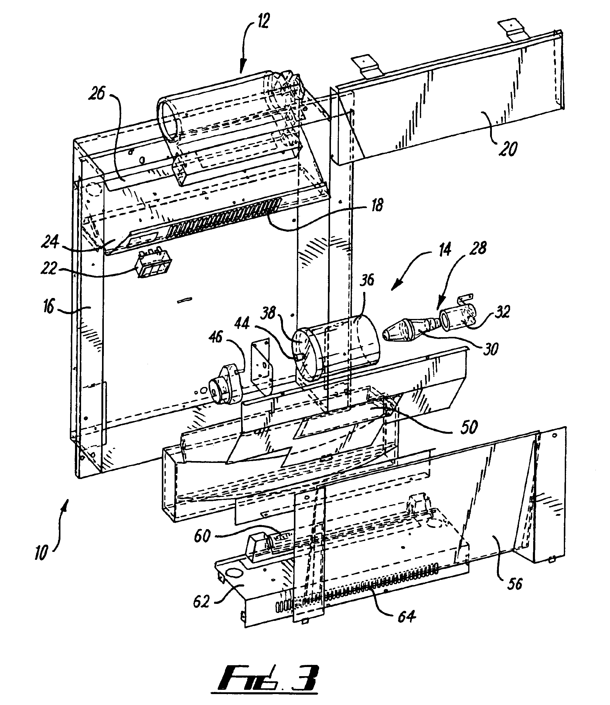
[0022]FIGS. 1-6 show an electric fire assembly 10 comprising an electric heater 12 and a flame effect arrangement 14. The assembly 10 comprises a conventional rectangular cross-section casing 16. The heater 12 is located at an upper part of the casing 16 and is in the form of an essentially conventional electric fan arrangement directing heated air forwards and downwards through a vent 18 beneath a cowling 20. Controls 22 for the assembly 10 are provided adjacent the vent 18. The heater 12 is mounted on a plate 24, which is inclined downwardly in a forward direction and has an opening 26 at its rear to receive air to be heated.

[0023]The flame effect arrangement 14 comprises a light source 28 in the form of a substantially point light source bulb 30. The bulb 30 is mounted in a holder 32 and extends into a pattern provider 34. The pattern provider 34 comprises a hollow cylindrical member 36 with an opaque end cap 38. A strip 40 of material best shown in FIG. 4 provides the walls of t...


PUM


Abstract

An electric fire assembly with a flame effect arrangement. The arrangement includes a bulb located in a hollow cylindrical member of opaque material with a plurality of flame shape cutouts. Light passes through the cutouts onto the rear surface of a screen to provide a flame effect as the member rotates.

Description

FIELD OF THE INVENTION[0001]This invention concerns improvements in or relating to electric fire assemblies, and particularly but not exclusively to such assemblies which provide a visual simulation of a natural fire, and also to improvements in or relating to flame effect arrangements.BACKGROUND OF THE INVENTION[0002]A number of electric fire assemblies, which provide a visual simulation of a natural fire by way of a flame effect have previously been proposed. In general, these have thus been relatively bulky and many have included quite complex arrangements and have thus been quite expensive to manufacture. Also the flame effect provided has often not always been wholly satisfactory.[0003]There is a demand for a fire simulation device that combines superior performance and low costs. The present invention satisfies the demand.SUMMARY OF THE INVENTION[0004]According to the present invention there is provided an electric fire assembly comprising an electric heater and a flame effect...

Claims


Application Information

Patent Timeline
IPC IPC(8): F24C7/00
CPCF24C7/004Y10S362/806
Inventor RAVNBO-WEST, PAULCRESSWELL, LEEGREEN, MICHAEL JOHNCADD, MITCHELL LEEBERRISFORD, ROYREGAN, KEVIN
Owner GHP GRP
Features
  • R&D
  • Intellectual Property
  • Life Sciences
  • Materials
  • Tech Scout
  • Unparalleled Data Quality
  • Higher Quality Content
  • 60% Fewer Hallucinations
Learn More