
Fan holder and components cooling duct assembly

a cooling duct and fan holder technology, applied in the direction of lighting and heating apparatus, electric apparatus casings/cabinets/drawers, instruments, etc., can solve the problems of component failure, component overheating of heat generating computer components, and reducing the operating effectiveness of components

Active Publication Date: 2005-11-29
ORACLE INT CORP
View PDF11 Cites 39 Cited by
  • Summary
  • Abstract
  • Description
  • Claims
  • Application Information

AI Technical Summary

Problems solved by technology

Without proper cooling, heat generating computer components may overheat.
Overheating of computer components may reduce operating effectiveness of the components and lead to component failure.
System fans (e.g., fans coupled to the computer system chassis) typically do not provide enough air flow directed to or from specific computer components to provide proper cooling for those specific components.
Air ducts used to direct air flow toward components may be cumbersome to install and may tend to decrease the serviceability of (i.e., inhibit access to) the components.
Removing the duct in such a manner can be time consuming and cumbersome.
In addition, repeated use of screws or snaps may lead to loss of parts (e.g., screws) or breakage and / or failure of the screws, screw threads, or snaps.
Some of these components may lack access (e.g., surface area) for certain types of air direction means to be coupled to the components.

Method used


Image

  • Fan holder and components cooling duct assembly
  • Fan holder and components cooling duct assembly
  • Fan holder and components cooling duct assembly

Examples


Embodiment Construction

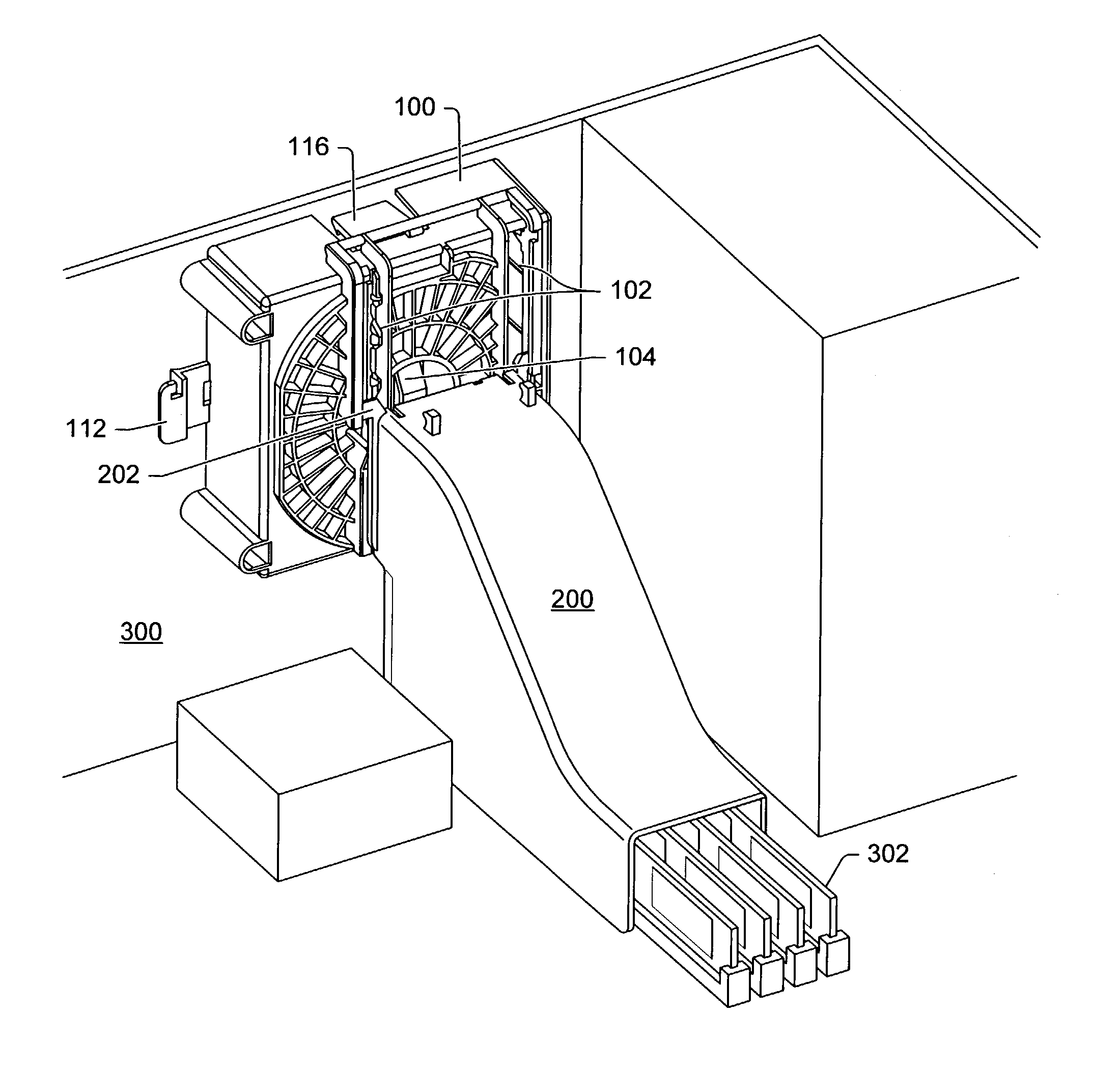
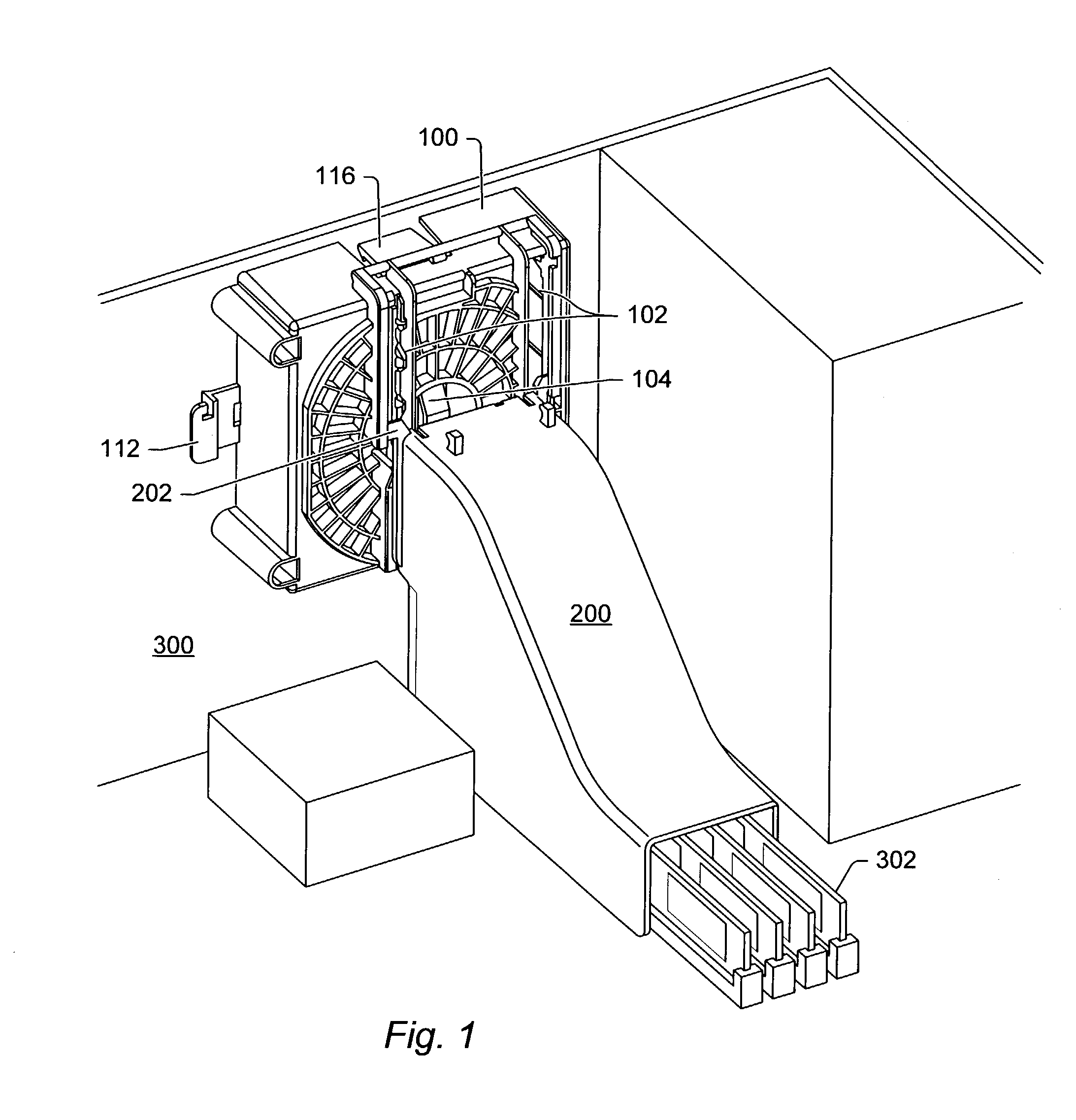
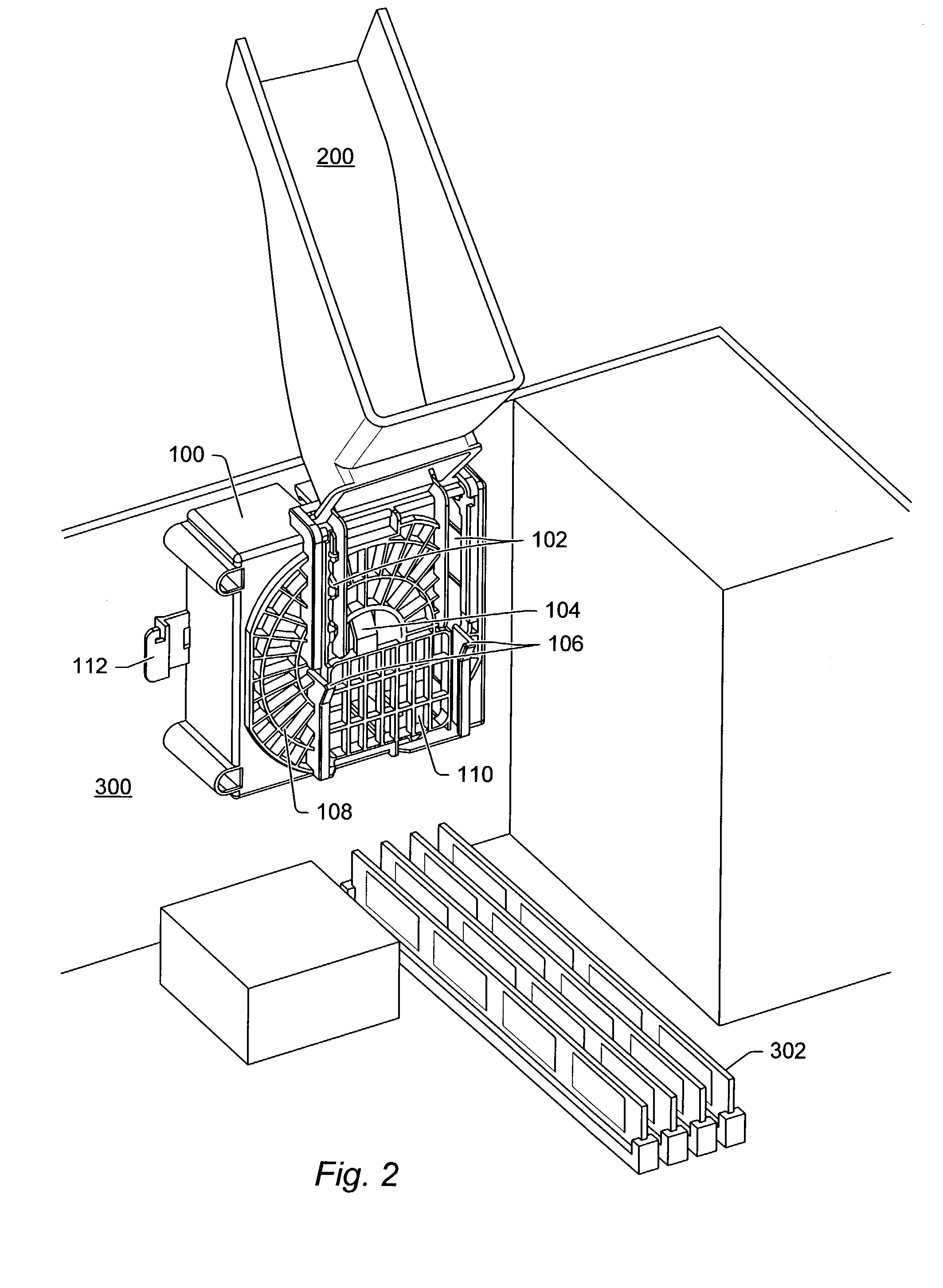
[0021]FIG. 1 depicts a perspective view of an embodiment of a cooling apparatus coupled to a computer chassis in a cooling position. The cooling apparatus may include fan assembly 100 and duct 200. Fan assembly 100 may be coupled to computer chassis 300. Fan assembly 100 may be coupled computer chassis 300 by any means typical in the art. In some embodiments, fan assembly 100 is coupled to chassis 300 with screws, bolts, clips, or any other suitable mechanism. In an embodiment, fan assembly 100 may include snaps or hooks that fit under a lip on chassis 300.

[0022]Duct 200 may be coupled to fan assembly 100. In certain embodiments, duct 200 may be slidably coupled to fan assembly 100. Fan assembly 100 may have one or more grooves 102. Duct 200 may be coupled to grooves 102. Duct 200 may have extensions 202. Extensions 202 may slide in grooves 102 so that duct 200 moves along a length of the grooves. In embodiments described herein, two grooves 102 and two extensions 202 are used. Any ...


PUM


Abstract

A computer component cooling apparatus is described. The cooling apparatus may include a fan assembly. The fan assembly may be coupled to a computer chassis. A duct may be slidably coupled to the fan assembly. The duct may be positioned in at least two positions on the fan assembly without being uncoupled from the fan assembly. In a first position, the duct may direct a flow of air over one or more computer components. In a second position, the duct may allow access to the one or more of the computer components.

Description

BACKGROUND[0001]1. Field of the Invention[0002]This invention generally relates to the field of cooling computer components. Certain embodiments relate to an apparatus for directing a flow of air over one or more computer components located in a computer chassis.[0003]2. Description of the Related Art[0004]Numerous components located inside a computer chassis require proper cooling to operate effectively. Without proper cooling, heat generating computer components may overheat. Overheating of computer components may reduce operating effectiveness of the components and lead to component failure. System fans (e.g., fans coupled to the computer system chassis) typically do not provide enough air flow directed to or from specific computer components to provide proper cooling for those specific components. Generally, some type of duct coupled to a fan or other air direction means has to be provided to properly cool specific components.[0005]Air ducts used to direct air flow toward compon...

Claims


Application Information

Patent Timeline
Patent Type & Authority Patents(United States)
IPC IPC(8): G06F1/20
CPCG06F1/20
Inventor BROVALD, RUSSELL K.ONG, BRETT C.KIM, DONGGYU
Owner ORACLE INT CORP
Learn More