Clip

a clip and clip technology, applied in the field of clips, can solve the problems of not being able to tightly hold the money, two arms are not easy to manipulate, and the money clip is not effective as a money clip,

Inactive Publication Date: 2005-12-06
HALSTEAD PAUL ANTHONY
View PDF5 Cites 258 Cited by
  • Summary
  • Abstract
  • Description
  • Claims
  • Application Information

AI Technical Summary

Benefits of technology

[0016]The clip may also be provided with a lock or catch to prevent unauthorised release of the first and second portions.

Problems solved by technology

The two arms are not easy to manipulate in order to insert or withdraw the banknotes from between the arms of the money clip.
The inherent disadvantage of this arrangement is that it is not effective as a money clip.
However weak magnetics will result in the money clip being unable to tightly hold the money.
With a large bundle of notes the prior art money clip may be completely ineffective.
However, it may difficult in such an arrangement to prise the two sheets apart in order to access the money.

Method used


Image

  • Clip
  • Clip
  • Clip

Examples


Embodiment Construction

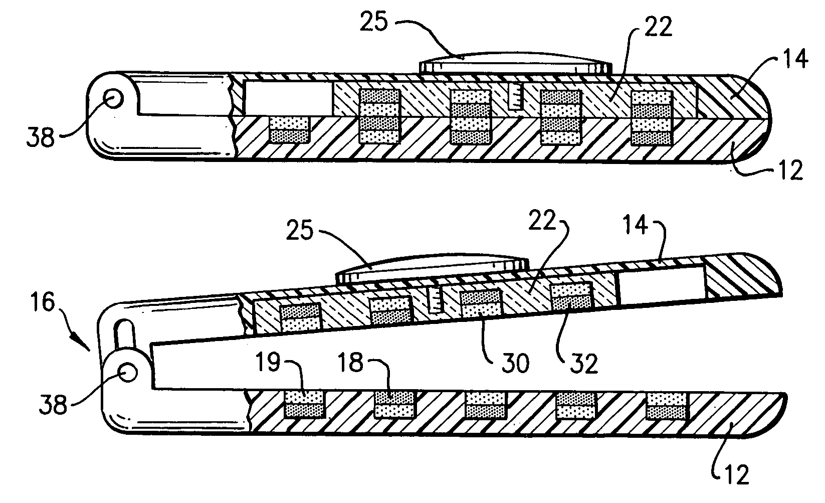
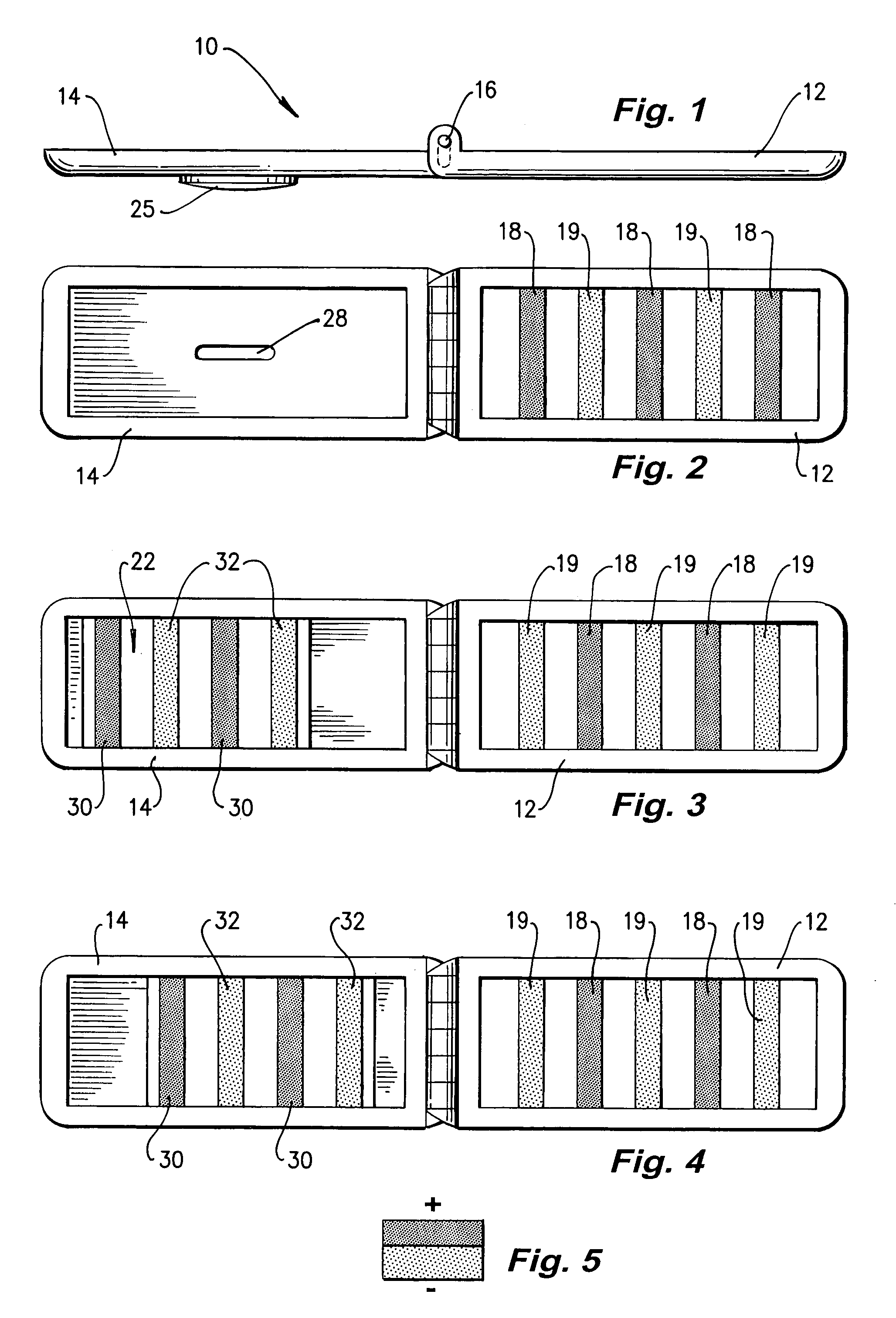
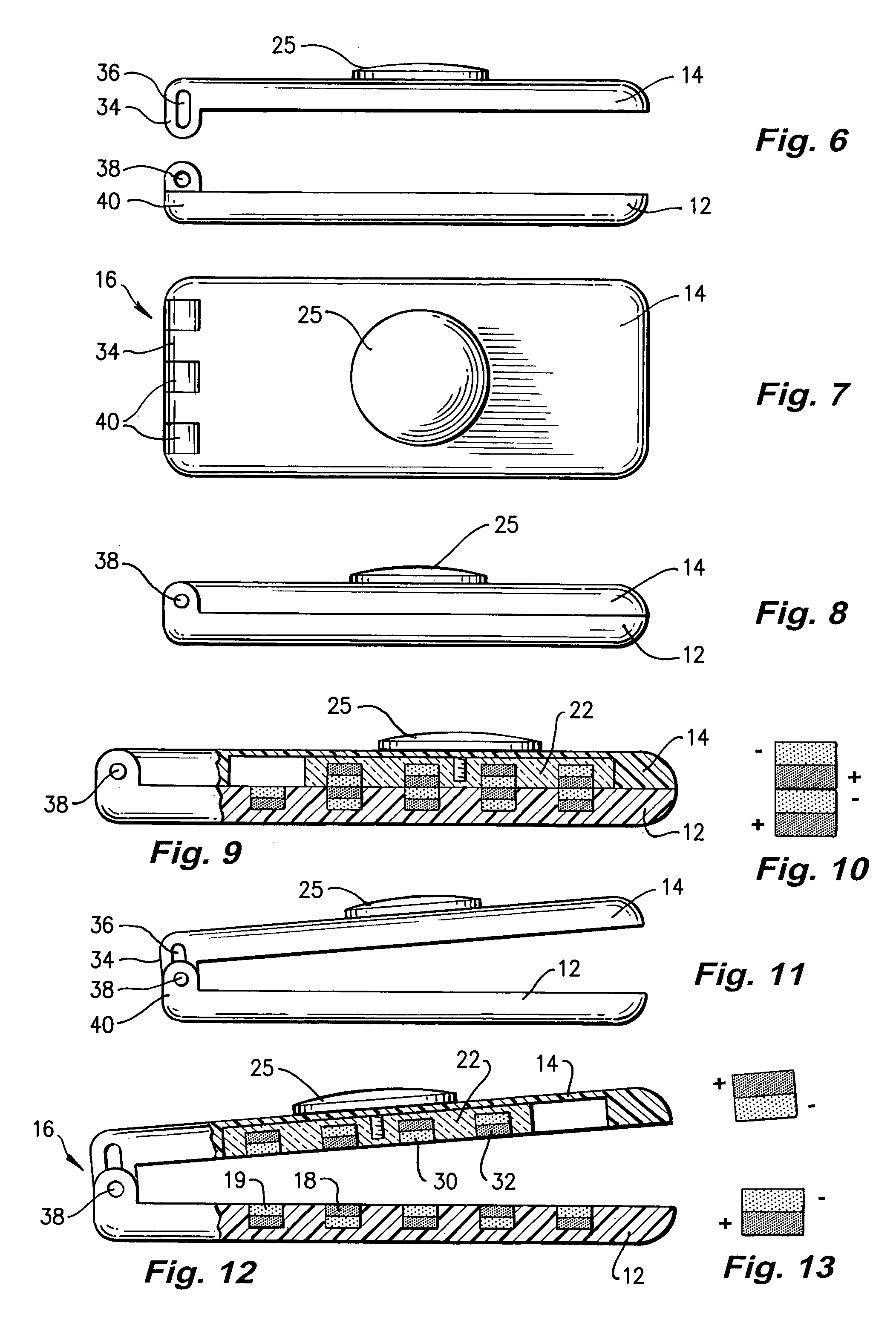
[0032]The clip 10 illustrated in FIG. 1 comprises a first clasp portion 14 and a second clasp portion 12 which are pivotably connected through pivot 16. The arrangement of the two clasp portions 12, 14 is such that the clasp portions 12, 14 are able to be separated to form an angle of 180 degrees and to form the closed configuration illustrated in FIG. 6. Each of the clasp portions 12, 14 is constructed from metal and is substantially planar and rectangular in plan as illustrated in FIG. 2. Further, as illustrated in FIG. 2, the second clasp portion 12 is provided with a series of spaced bands of magnetic material 18, 19. The bands 18, 19 extend across the width of the second clasp portion 12. FIG. 2 illustrates the polarity of bands 18, 19 by shading. Bands 18 have an upper surface which is positive as depicted by dark shading and a lower surface (not shown) which is negative. On the other hand, the light shading of the bands 19 illustrates negative polarity on the top surface with...


PUM


Abstract

A clip (10) for holding banknotes has a first clasp portion (14) and a second clasp portion (12) for holding banknotes therebetween. The first clasp portion (14) has a first magnetic portion (22) including magnetic material (30,32) and the second clasp portion has a second magnetic portion including magnetic material (18,19). The first magnetic portion (22) is moveable relative to the second magnetic portion between: a closed position whereby the interaction of the magnetic material of the first magnetic portion (30,32) and second magnetic portion (18,19) is such that there is a net force of attraction to hold the first and second clasp portions (14,12) together; and an open position whereby the first and second clasp portions (14,12) are released apart.

Description

FIELD OF THE INVENTION[0001]The present invention relates to a clip. In particular although not exclusively, the invention relates to a money clip for holding banknotes. While the invention has been described particularly in regard to banknotes, the clip may be used in relation to other security documents, such as passports, bonds, letters of credit etc.BACKGROUND TO THE INVENTION[0002]A conventional money clip typically comprises a piece of metal bent over double to form two arms which are resiliently sprung together between which banknotes may be positioned. The two arms are not easy to manipulate in order to insert or withdraw the banknotes from between the arms of the money clip.[0003]U.S. Pat. No. 5,794,767 illustrates a money clip comprised of two rubber sheets which are foldable to overlap each other. Each sheet has rubberised magnetic material which attract to hold banknotes therebetween. The inherent disadvantage of this arrangement is that it is not effective as a money cl...

Claims


Application Information

Patent Timeline
Patent Type & Authority Patents(United States)
IPC IPC(8): A45C1/06
CPCA45C1/06Y10T24/32A45C2001/062
Inventor HALSTEAD, PAUL ANTHONY
Owner HALSTEAD PAUL ANTHONY
Why Eureka
Try Eureka