Fluid flow measuring device and method of manufacturing thereof

a technology of fluid flow measurement and measuring device, which is applied in the direction of survey, borehole/well accessories, instruments, etc., can solve the problems of misleading and non-representative readings, difficult detection of additional water entering the wellbore, and other severe limitations

a technology of fluid flow measurement and measuring device, which is applied in the direction of survey, borehole/well accessories, instruments, etc., can solve the problems of misleading and non-representative readings, difficult detection of additional water entering the wellbore, and other severe limitations

US6971271B2Inactive Publication Date: 2005-12-06REM SCI ENTERPRISES

Image

  • Fluid flow measuring device and method of manufacturing thereof
  • Fluid flow measuring device and method of manufacturing thereof
  • Fluid flow measuring device and method of manufacturing thereof

Examples


Embodiment Construction

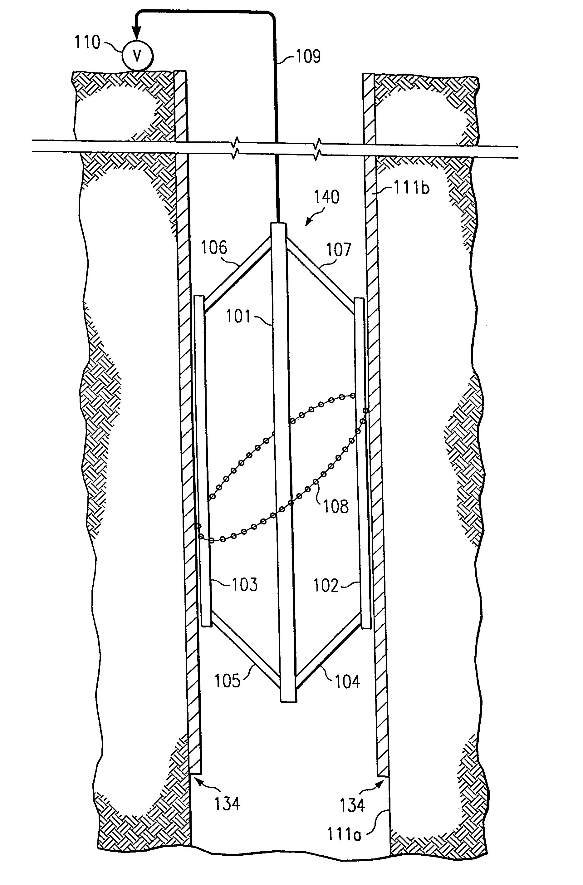
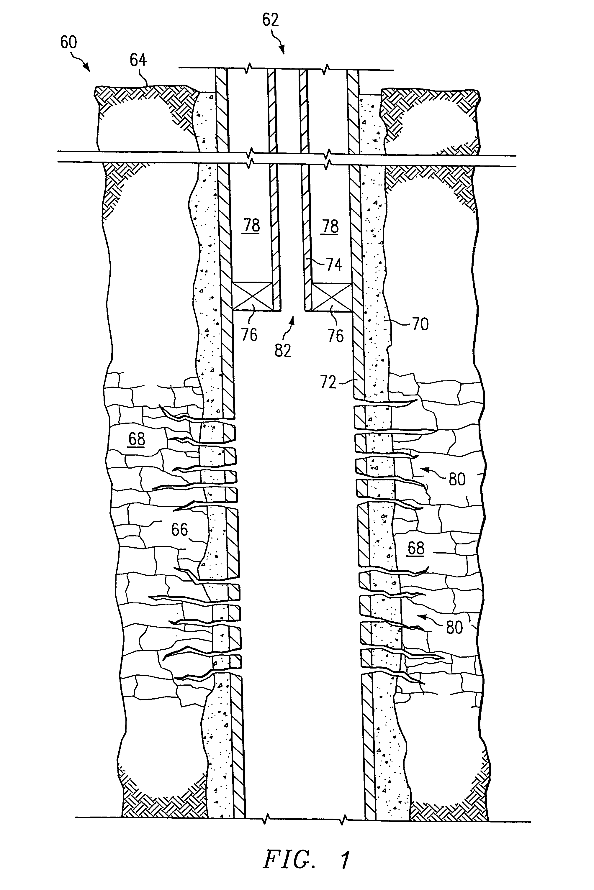
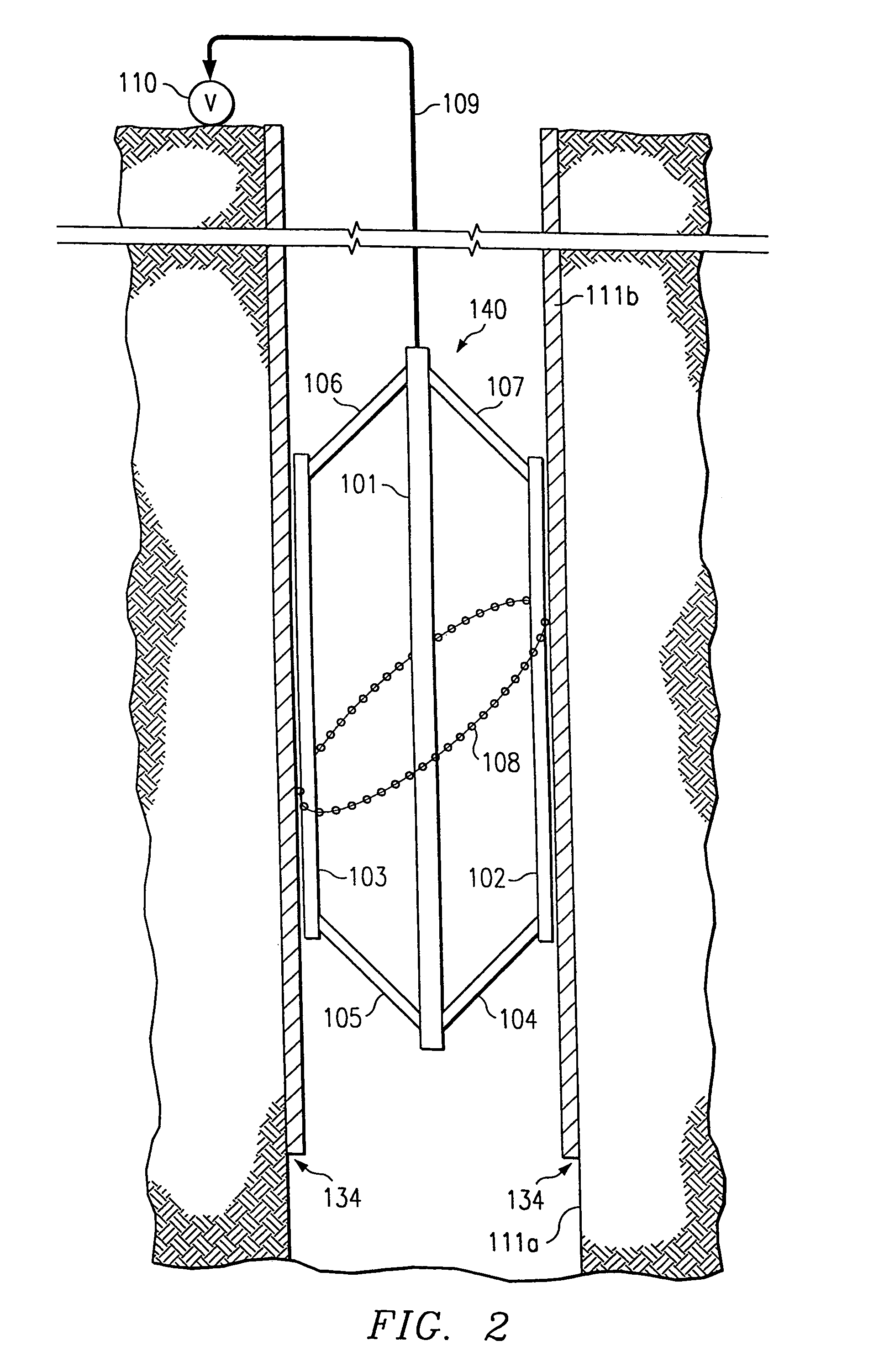
[0045]There are many disadvantages in prior art methods and tools for detecting water flow. For example, prior art devices and techniques are sensitive to all fluids, including water, oil and gas, which leads to ambiguity in the determination of what fluid is involved. Fluid entry or exit must be inferred from the wellbore from measurements made in the center of the borehole in complex and changing flow regimes above and below the point of interest, and the assumption that any change is due to inflow or outflow must be made. Prior art methods do not directly sense water entering or leaving the wellbore, and are sensitive to water already in borehole, whether the water is moving or not. The determination of which type of fluid, water, oil or gas, is entering or exiting the borehole must be inferred by looking at changes in measurements made above and below the entry or exit and inferring which type of fluid made the changes. The measurements are made in the center of the borehole in ...


PUM

PropertyMeasurementUnit
depthaaaaaaaaaa
widthaaaaaaaaaa
diameteraaaaaaaaaa

Abstract

In a borehole logging tool, the flow of conductive fluid into or out of a wellbore at the wellbore wall is detected and measured with a sensor loop proximate the borehole inner wall. The sensor loop includes a series of contiguous sensors that act as electromagnetic flowmeters and provide fluid measurements covering the entire circumference of the sensor loop. The sensor loop includes an elastic element that forces the sensor loop outward to maintain pressure along the sensor loop circumference against the interior borehole wall. The sensor loop is designed to lie at a non-perpendicular angle to the wellbore axis, and mechanical arms press the top and bottom of the loop against the borehole inner wall.

Description

[0001]This application is a continuation of U.S. application Ser. No. 10 / 600,053, filed Jun. 20, 2003, entitled “Fluid Flow Measuring Device and Method of Manufacturing Thereof,” now U.S. Pat. No. 6,779,407, to issue Aug. 24, 2004, which application is a divisional of U.S. application Ser. No. 09 / 880,402, filed Jun. 13, 2001, entitled “Conductive Fluid Logging Sensor and Method,” now U.S. Pat. No. 6,711,947, issued Mar. 30, 2004, which applications are incorporated herein by reference.TECHNICAL FIELD[0002]This invention relates generally to oil and gas well production logging sensors and methods, and more particularly to a sensing device and method for detecting fluid influx into a well.BACKGROUND[0003]An oil and gas well is shown in FIG. 1 generally at 60. Well construction involves drilling a hole or borehole 62 in the surface 64 of land or ocean floor. The borehole 62 may be several thousand feet deep, and drilling is continued until the desired depth is reached. Fluids such as o...

Claims


Application Information

Patent Timeline
06 Dec 2005
Publication
US6971271B2
IPC
E21B47/01; E21B47/10; G01F1/58
CPC
E21B47/011; E21B47/102; G01F1/588; G01F1/58; Y10T29/49007; E21B47/017; E21B47/113
Inventors
MAUTE, ROBERT E.