Guard and control apparatuses for sliding compound miter saw

a control apparatus and compound miter saw technology, which is applied in the direction of metal sawing devices, band saws, manufacturing tools, etc., can solve the problems of many conventional devices that have not met some or all of these objectives, are difficult to design, manufacture and maintain, and are often found to be heavy and overly complex, so as to prevent or substantially minimize damage to the fixed guard, prevent or minimize any tendency, and maximize the cutting depth of the workpi

Inactive Publication Date: 2005-12-06
BLACK & DECKER INC
View PDF55 Cites 52 Cited by
  • Summary
  • Abstract
  • Description
  • Claims
  • Application Information

AI Technical Summary

Benefits of technology

[0009]A return spring can be advantageously included in the guard linkage assembly for resiliently biasing the movable guard toward a normally closed position covering a maximum portion of the cutting periphery of the blade or cutter. Such return spring is preferably a torsional coil spring with one anchoring end or leg interconnected with the fixed guard or drive assembly (at a fixed location thereon) and an opposite end or leg interconnected with the movable guard (also at a fixed location thereon). An off-center spring enclosure, which is radially offset relative to the arbor shaft, is preferably included for restricting radial expansion of the torsional spring to directions away from the workpiece (on opposite sides of the arbor shaft from the workpiece) in order to maximize the workpiece cutting depth capacity of the saw blade or cutter.
[0010]Another optional but preferred feature of the invention is an arbor shaft cover that is pivotally interconnected with the fixed guard and that substantially prevents or minimizes any tendency of the arbor shaft nut, screw or other blade-securing fastener to work loose on, or free of, the arbor shaft. Such arbor cover can be pivoted out of the way to allow blade removal or blade changing by way of a releasable cover retaining fastener at one end of the pivotal cover, with such retaining fastener also optionally being configured to extend axially inside the fixed guard when tightened so as to act as one of a pair of blade calipers axially spaced from opposite sides of the blade or cutter. Such calipers thereby prevent or substantially minimize damage to the fixed guard in the event of a bent or deflected blade or cutter.

Problems solved by technology

Unfortunately, many conventional devices have proved to be deficient in meeting some or all of these objectives, or have required burdensome multiplicities of parts or components in order to achieve them.
Thus, many of such conventional devices have also often been found to be heavy and overly complex, difficult and expensive to design, manufacture and maintain, as well as requiring large spaces in which to operate them.
In some cases, meeting these objectives has also resulted in unduly limiting cutting capacities.

Method used


Image

  • Guard and control apparatuses for sliding compound miter saw
  • Guard and control apparatuses for sliding compound miter saw
  • Guard and control apparatuses for sliding compound miter saw

Examples


Embodiment Construction

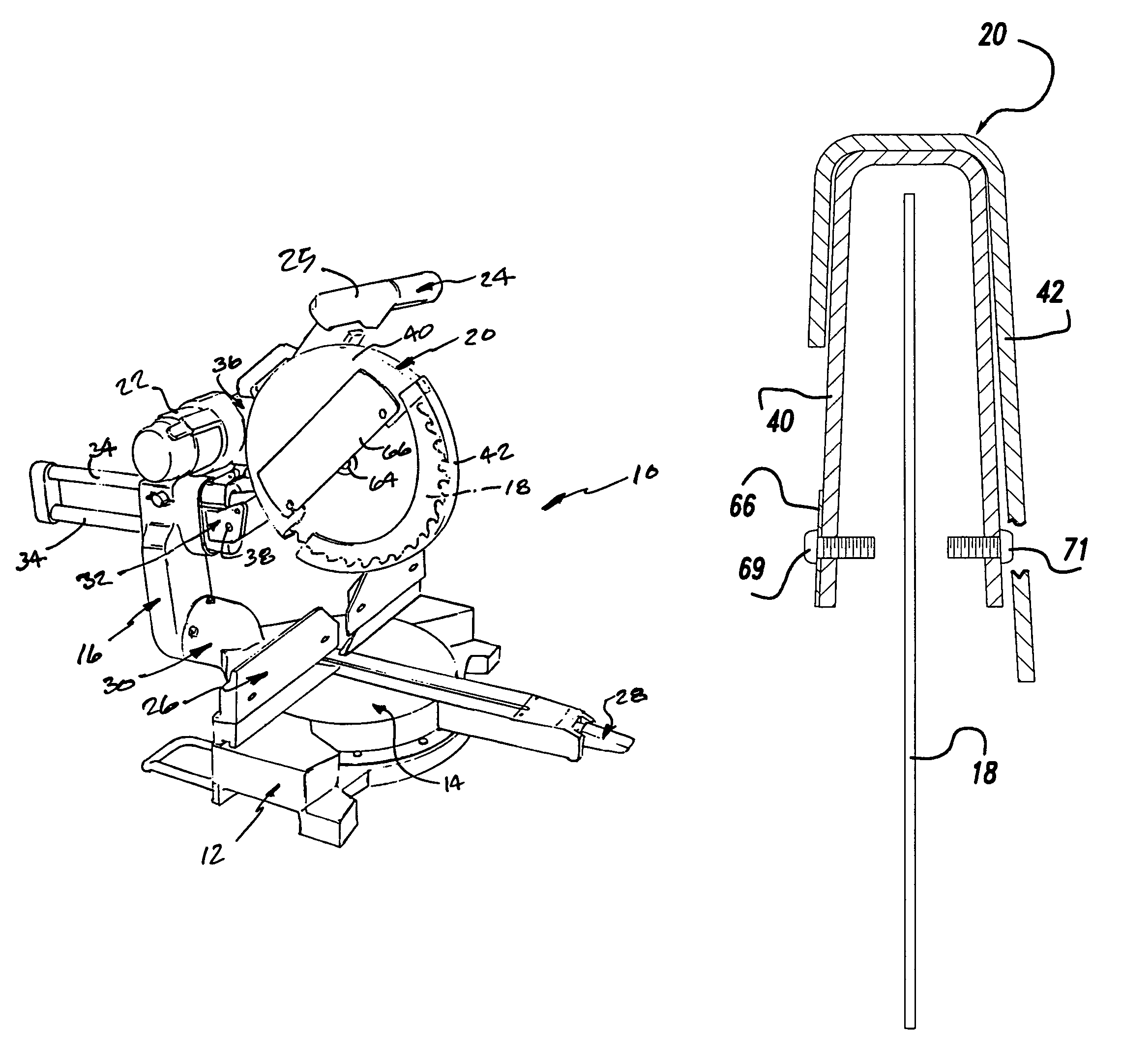
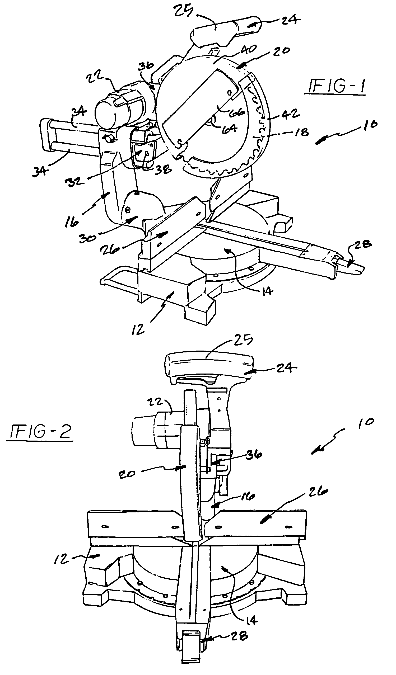
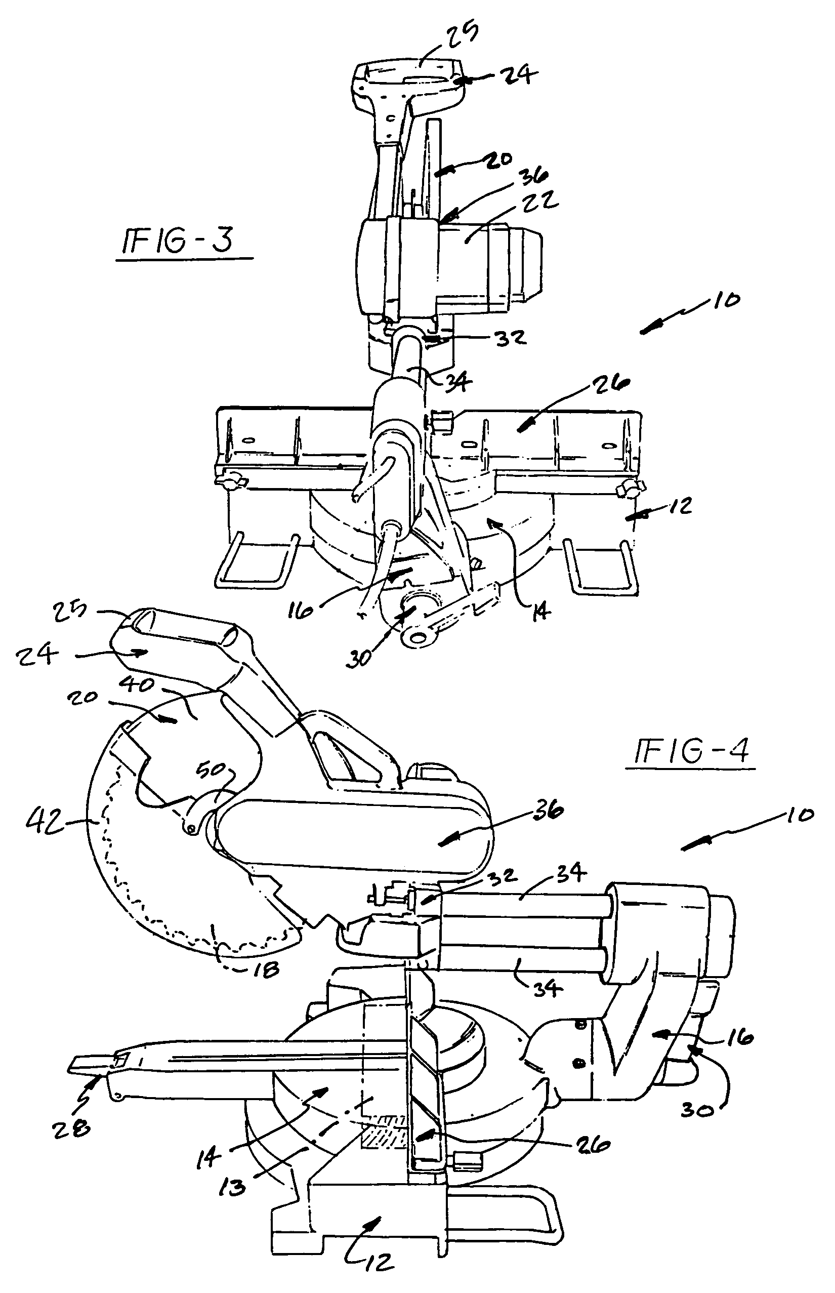
[0028]FIGS. 1 through 14b depict exemplary embodiments of a sliding compound miter saw according to the present invention, which is shown in the drawings merely for purposes of illustration. One skilled in the art will readily recognize, from the following description, taken in conjunction with the accompanying drawings and claims, that the principles of the invention are equally applicable to compound miter saws and / or chop saws of types other than that depicted in the drawings. Similarly, one skilled in the art will readily recognize that the principles of the invention may also be applicable to other workpiece cutting, forming or shaping devices.

[0029]In FIGS. 1 through 4, an exemplary sliding compound miter saw incorporating a cutter or blade guard mechanism, as well as other features according to the present invention, is designated generally by the reference numeral 10. The sliding compound miter saw 10 includes a base assembly 12, an angularly movable turntable or table assem...


PUM

PropertyMeasurementUnit
angleaaaaaaaaaa
sizesaaaaaaaaaa
anglesaaaaaaaaaa

Abstract

A guard assembly for a saw or other cutting device includes fixed and movable guards relatively pivotal by way of a linkage assembly having two links pivotally interconnected coaxially with a cam roller engageable with a cam surface for controlling relative guard movement. Other preferred features include a torsional coil guard return spring and spring enclosure that minimizes interference with workpiece cutting depth, an arbor shaft cover retention fastener that doubles, along with another caliper member, as a blade caliper set that prevents guard damage in the event of a bent or deflected blade or cutter, a drive assembly hold-down assembly for storage, and a horizontally-extending handle centered horizontally relative to the blade or cutter.

Description

[0001]This is a division of U.S. patent application Ser. No. 08 / 974,093, filed Nov. 19, 1997 now U.S. Pat. No. 6,182,548, which is a divisional of application Ser. No. 08 / 541,667, filed Oct. 10, 1995, now U.S. Pat. No. 5,724,875, issued Mar. 10, 1998.[0002]This patent application is related to a copending U.S. patent application Ser. No. 08 / 499,339, filed Jul. 7, 1995, entitled “Adjustable Fence For Compound Miter Saw”, the disclosure of which is hereby incorporated by reference herein.[0003]The present invention relates primarily to power chop-type saws, miter saws, compound miter saws or other power operated equipment or machinery utilizing a blade or other cutter for performing working operations on workpieces composed of wood, metal, plastic or other materials. More particularly, the present invention seeks to achieve various improvements in blade guard mechanisms for such power operated equipment, typically having a lower movable guard pivotally movable relative to a fixed uppe...

Claims


Application Information

Patent Timeline
Patent Type & Authority Patents(United States)
IPC IPC(8): B23D45/04B27G19/02
CPCB27G19/02Y10T83/7734Y10T83/7788Y10T83/8886
Inventor MEREDITH, DARYL S.PRICE, SCOTTSTUMPF, WILLIAM R.
Owner BLACK & DECKER INC
Why Eureka
Try Eureka