Method for manufacturing hair clipper blade

a manufacturing method and technology for hair clippers, applied in cutting tools, domestic applications, kitchen equipment, etc., can solve the problems of reducing the life of grindstones and pushing up the cost of blades

Inactive Publication Date: 2005-12-13
MATSUSHITA ELECTRIC WORKS LTD
View PDF7 Cites 34 Cited by
  • Summary
  • Abstract
  • Description
  • Claims
  • Application Information

AI Technical Summary

Benefits of technology

[0009]According to another aspect of the present invention, a method for manufacturing a hair clipper blade includes positioning a blank in a forward-feed mold. The blank is provided with a comb teeth shaped cutting edge portion. The blank with the cutting edge portion is moved to a next position. The cutting edge portion is forged to have an acute tip angle at the next position.

Problems solved by technology

Another problem is that because the amount to be cut by the grindstone 30 is also increased, the life of the grindstone is shortened and the blade cost is pushed up.

Method used


Image

  • Method for manufacturing hair clipper blade
  • Method for manufacturing hair clipper blade
  • Method for manufacturing hair clipper blade

Examples


Embodiment Construction

[0057]The embodiments will now be described with reference to the accompanying drawings, wherein like reference numerals designate corresponding or identical elements throughout the various drawings.

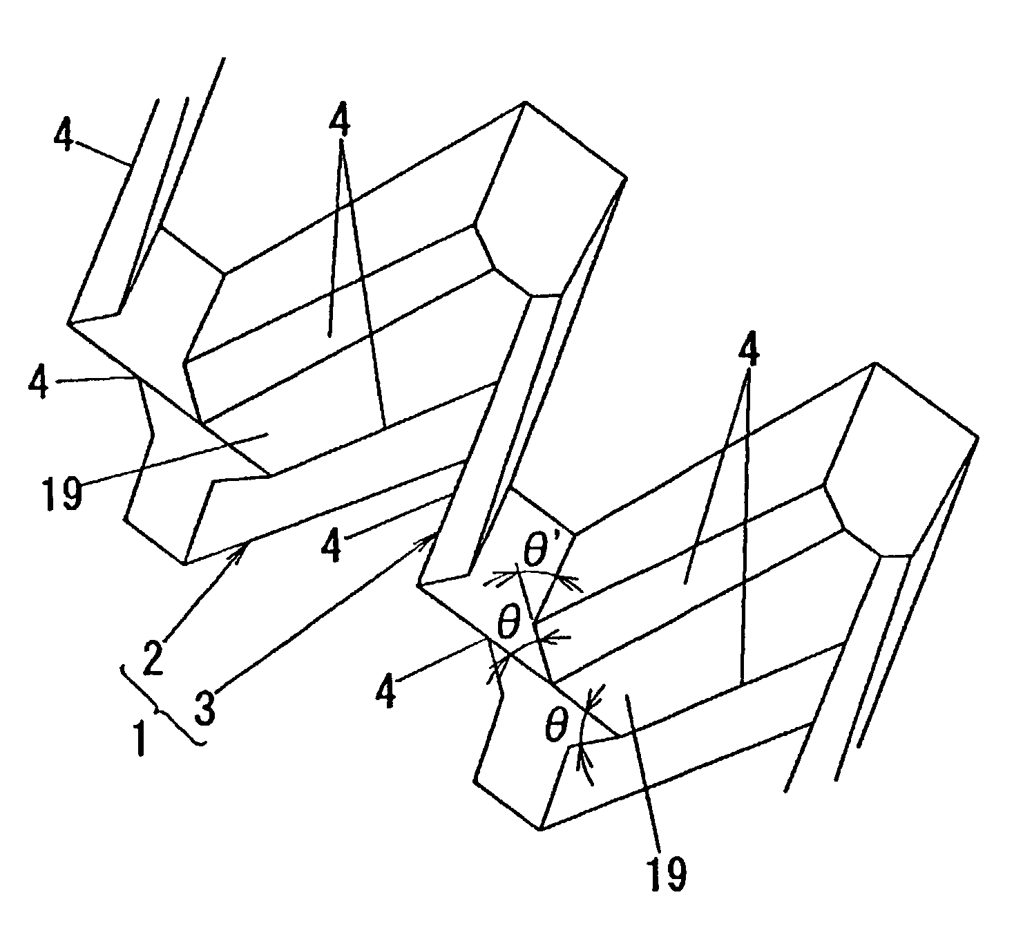
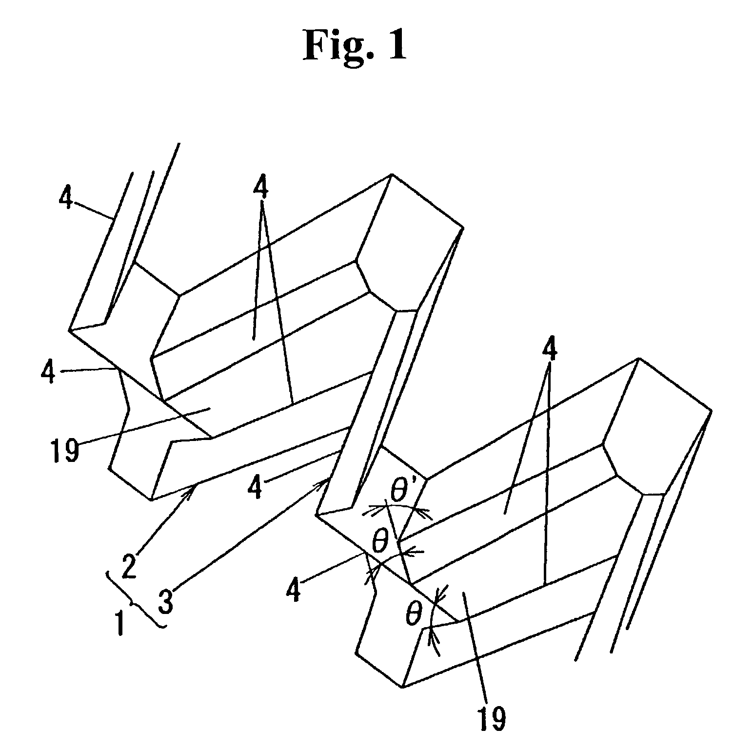
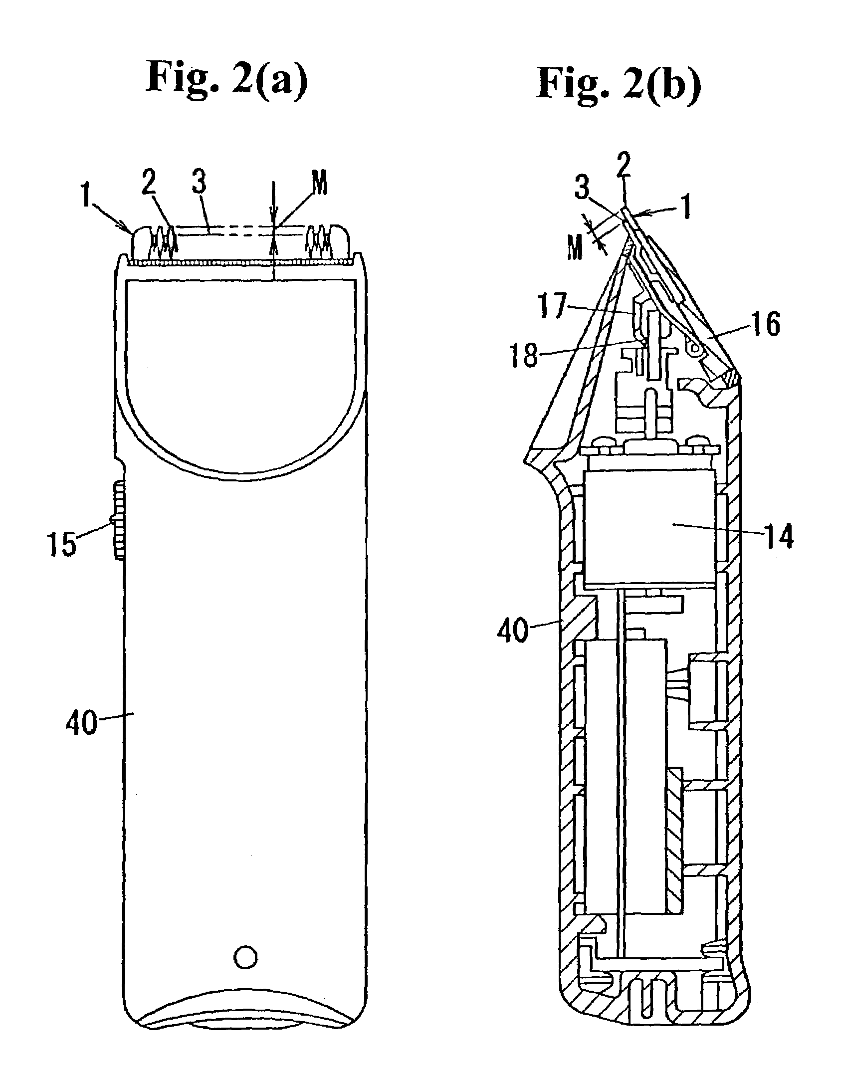
[0058]As shown in FIGS. 2(a), 2(b) and 3, an electric hair clipper according to an embodiment of the present invention includes a clipper body 40 which contains a motor 14, a power supply battery and an electric circuit. A hair clipper blade 1 which has a stationary blade 2 and a movable blade 3 each in the form of comb teeth is provided at a top of the body 40 as viewed in the drawings. A switch handle 15 is provided on a surface of the body 40. Upon operation of the switch handle 15, the movable blade 3 is reciprocally moved to cut hairs with comb teeth portions of both the stationary blade 2 and the movable blade 3. The stationary blade 2 and the movable blade 3 are made from, for example, a metal or an intermetallic compound.

[0059]The hair clipper blade 1 is constructed, as shown in ...


PUM


Abstract

A method for manufacturing a hair clipper blade includes providing a blank with a comb teeth shaped cutting edge portion, and forging the cutting edge portion to have an acute tip angle.

Description

CROSS-REFERENCE TO RELATED APPLICATIONS[0001]The present application claims priority under 35 U.S.C. §119 to Japanese Patent Application No. 2002-118241, filed Apr. 19, 2002. The contents of this application are incorporated herein by reference in their entirety.BACKGROUND OF THE INVENTION[0002]1. Field of the Invention[0003]The present invention relates to a method for manufacturing a hair clipper blade.[0004]2. Discussion of the Background[0005]An edge cutting method using a grindstone 30, shown in FIGS. 22(a)–22(c), is conventionally known as one typical example of methods of manufacturing a hair clipper blade 1′ for use in a manual or electric hair clipper. In FIG. 22(a), β denotes an angle of the grindstone 30 and θ2 denotes an edge cutting angle. Also, γ in FIG. 22(b) denotes an edge groove angle, and θ3 in FIG. 22(c) denotes a tip angle of a cutting edge portion 4.[0006]To increase sharpness of the hair clipper blade 1′, the edge cutting angle θ2 must be finished into an acut...

Claims


Application Information

Patent Timeline
Patent Type & Authority Patents(United States)
IPC IPC(8): B21D53/64B21K11/00B26B19/00B26B19/06
CPCB26B19/06B26B19/3846B26B19/3893B21K5/12
Inventor YANOSAKA, MASAMINISHIMURA, YOSHIFUMI
Owner MATSUSHITA ELECTRIC WORKS LTD
Why Eureka
Try Eureka