Rack mount assembly

a technology for racks and racks, applied in the direction of dismountable cabinets, furniture parts, movable shelf cabinets, etc., can solve the problems of interference between vertically adjacent computer equipment enclosures and difficult installation

Inactive Publication Date: 2005-12-13
HEWLETT PACKARD DEV CO LP
View PDF25 Cites 93 Cited by
  • Summary
  • Abstract
  • Description
  • Claims
  • Application Information

AI Technical Summary

Problems solved by technology

A consideration with conventional installation of rack mount assemblies is difficulty of installation.
Either way is awkward.
Vertical misalignment of the rack mount assemblies could cause interference between vertically adjacent computer equipment enclosures.

Method used


Image

  • Rack mount assembly
  • Rack mount assembly
  • Rack mount assembly

Examples


Embodiment Construction

[0019]In the following detailed description and in the several figures of the drawing, like elements are identified with like reference numerals.

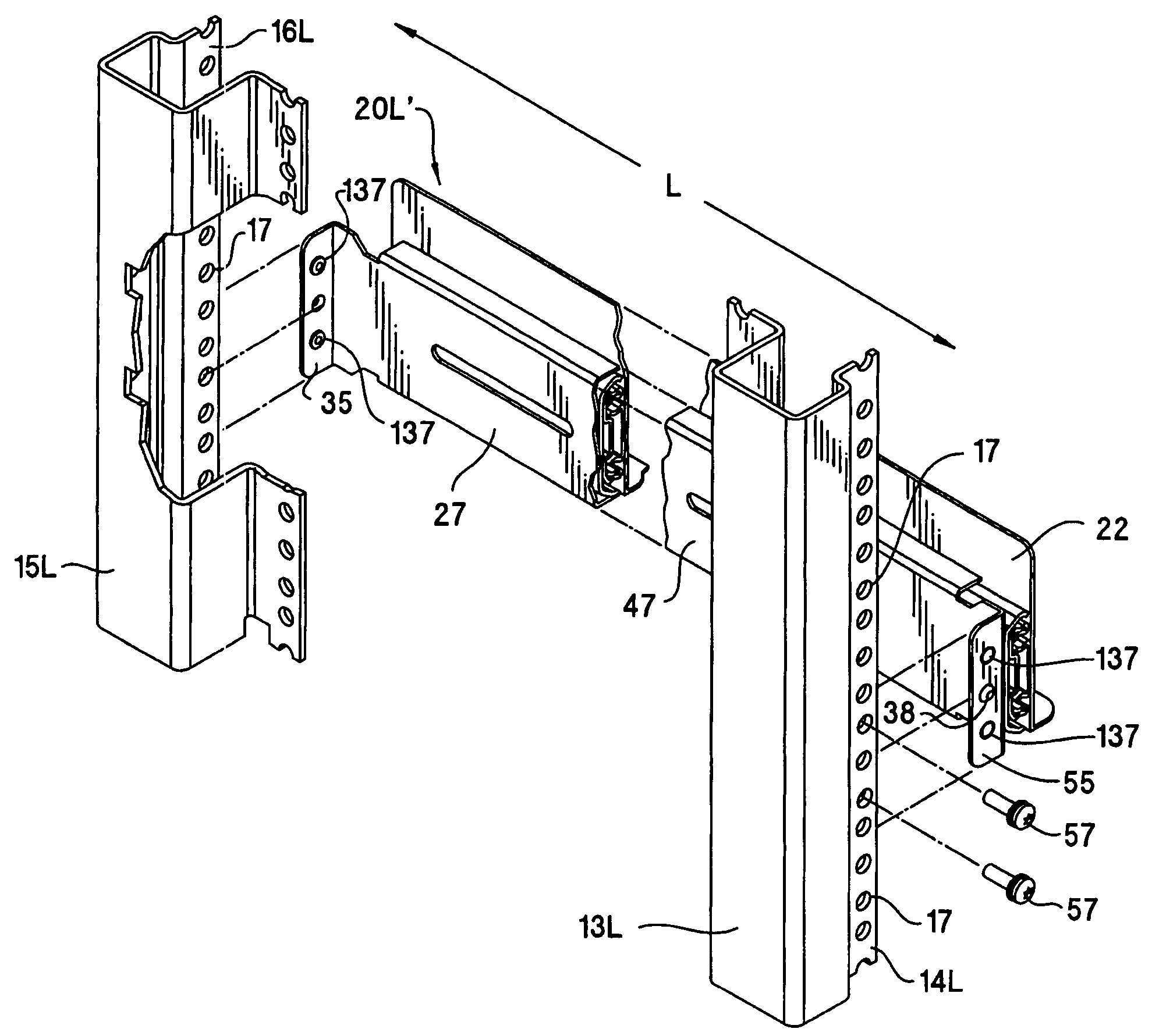
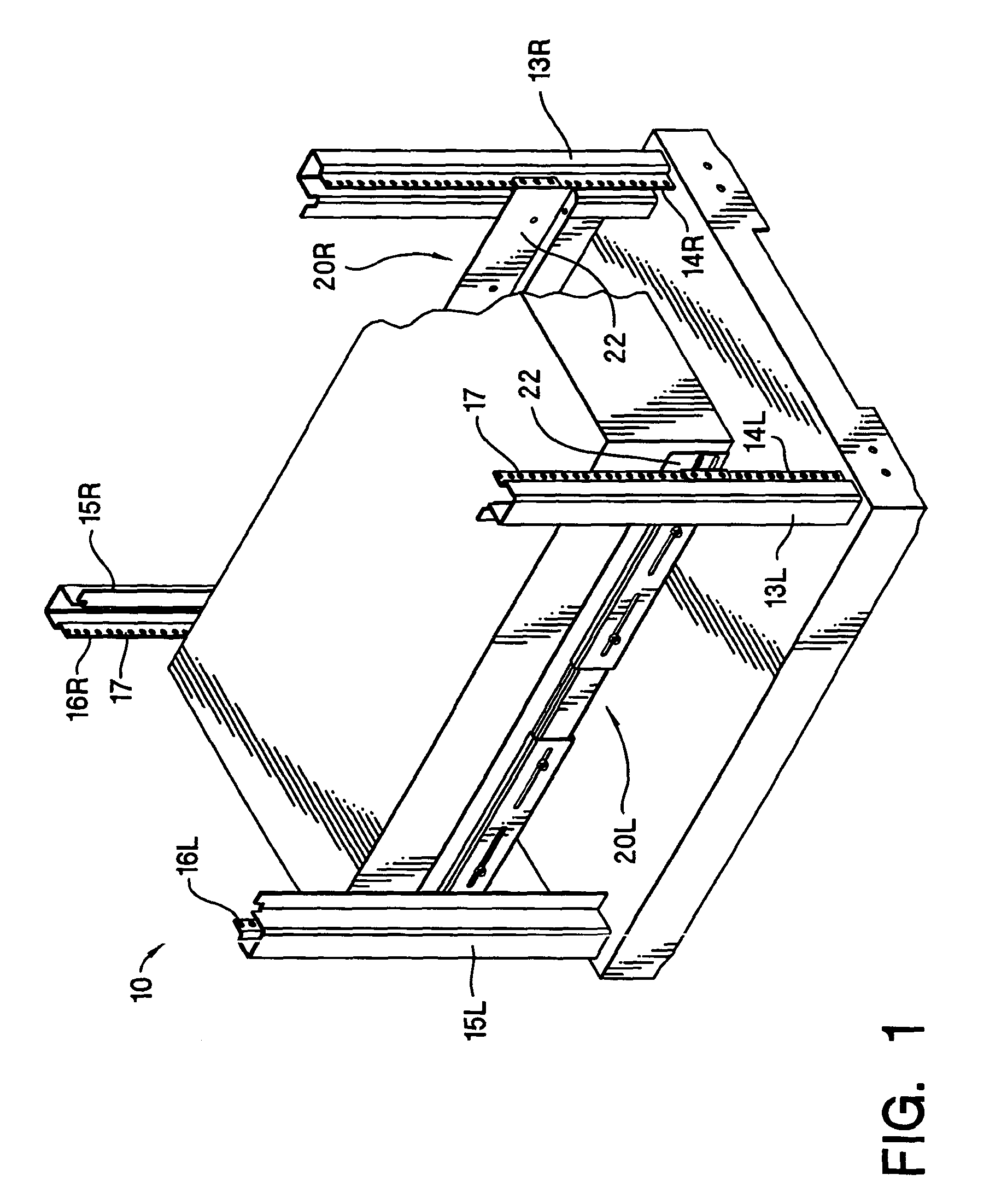
[0020]Referring now to the FIG. 1, set forth therein is a schematic perspective view of rack system 10 that incorporates a left rack mount assembly 20L and a right rack mount assembly 20R in accordance with the invention. The rack system 10 more particularly includes a frame comprised of front columns 13L, 13R and rear columns 15L, 15R. The front columns 13L, 13R respectively include left and right front column flanges 14L, 14R in which are formed apertures 17, and the rear columns 15L, 15R also respectively include left and right rear column flanges 16L, 16R in which are formed apertures 17. Conventionally, the front column flanges 14L, 14R are coplanar, and the rear column flanges 16L, 16R are coplanar. Also conventionally, the column flanges when viewed from above are located at the vertexes of a rectangle.

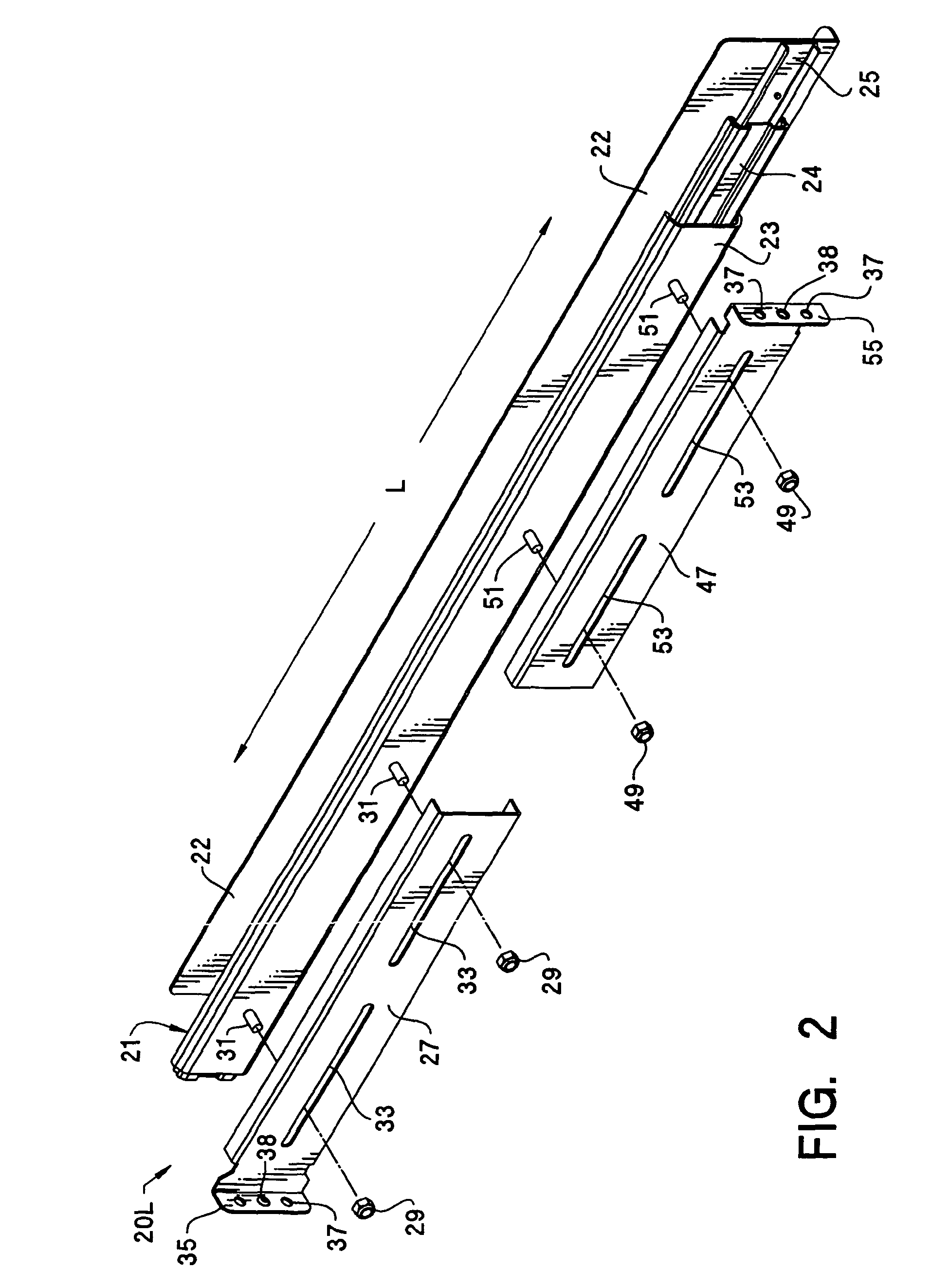
[0021]In accordance with the in...


PUM


Abstract

A rack mount assembly for supporting a computer enclosure in a rack system having vertical apertured column flanges. The rack mount assembly includes an elongated mount adapter having mounting flanges disposed at each end thereof. Each mounting flange includes an alignment protrusion that is configured to fit in a corresponding aperture in one of the column flanges of the rack system. The elongated mount adapter comprises, for example, a slide mechanism or a rack rail.

Description

CROSS-REFERENCE TO RELATED APPLICATIONS[0001]This is a Continuation of U.S. patent application Ser. No. 09 / 428,306, filed on Oct. 27, 1999, now U.S. Pat. No. 6,681,942, which is incorporated herein by reference.BACKGROUND OF THE INVENTION[0002]The disclosed invention relates generally to electronic equipment rack systems, and more particularly to a rack mount system that is self-aligning when installed.[0003]An electronic equipment rack system is an equipment supporting structure that includes four vertically oriented support columns, each having an apertured column flange. The support columns are fixedly located relative to each other so as to be at the corners of a rectangle, whereby two support columns are at a front of the rack system while two support columns are at a rear of the rack system. Thus, each of left and right sides of the rack system includes a front support column and a rear support column.[0004]A left side rack mount assembly and a right side rack mount assembly a...

Claims


Application Information

Patent Timeline
Patent Type & Authority Patents(United States)
IPC IPC(8): A47B88/04H05K7/14
CPCA47B88/044H05K7/1421H05K7/1489A47B88/43
Inventor HANEY, GEROME A
Owner HEWLETT PACKARD DEV CO LP
Why Eureka
Try Eureka