Cam-wedge locking mechanism

a locking mechanism and wedge technology, applied in the field of locking mechanisms, can solve the problems of increasing the risk of patient injury, difficult positioning of the retractor at this location, and difficult manipulation and positioning of the current retractor

Inactive Publication Date: 2005-12-13
MINNESOTA SCI
View PDF18 Cites 18 Cited by
  • Summary
  • Abstract
  • Description
  • Claims
  • Application Information

AI Technical Summary

Problems solved by technology

Current retractors are not easy to manipulate and position over the surgical incision because the arm is typically a solid inflexible rod.
Clamping mechanisms to lock the retractors in a precise location are typically cumbersome and require complex maneuvering that may increase the risk of injury to the patient.
Positioning the retractor at this location remains challenging since the clamping device may be difficult to operate, or be located at a place that may increase the risk of contamination to the patient.

Method used


Image

  • Cam-wedge locking mechanism
  • Cam-wedge locking mechanism
  • Cam-wedge locking mechanism

Examples


Embodiment Construction

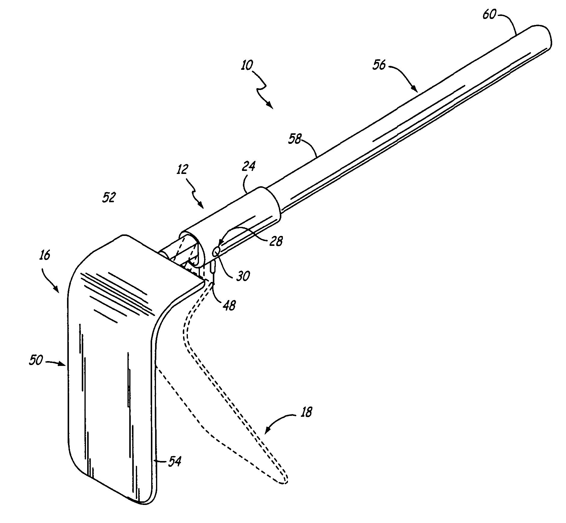
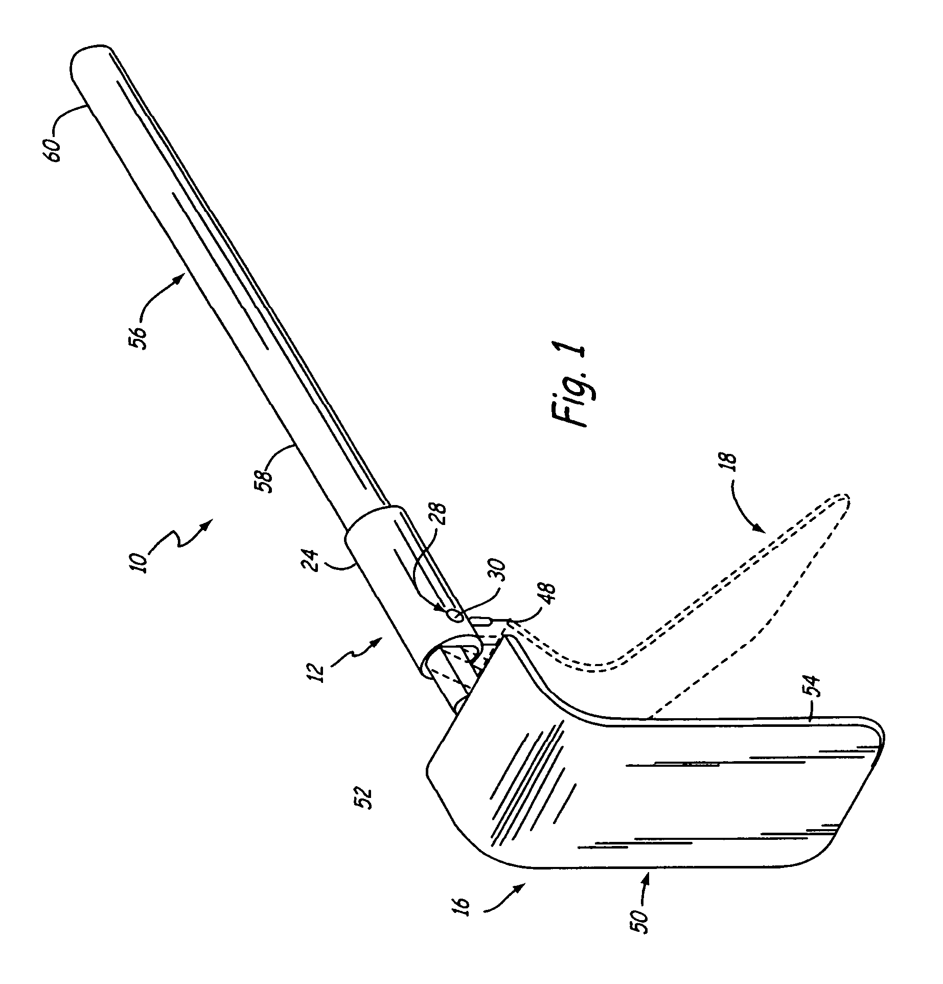
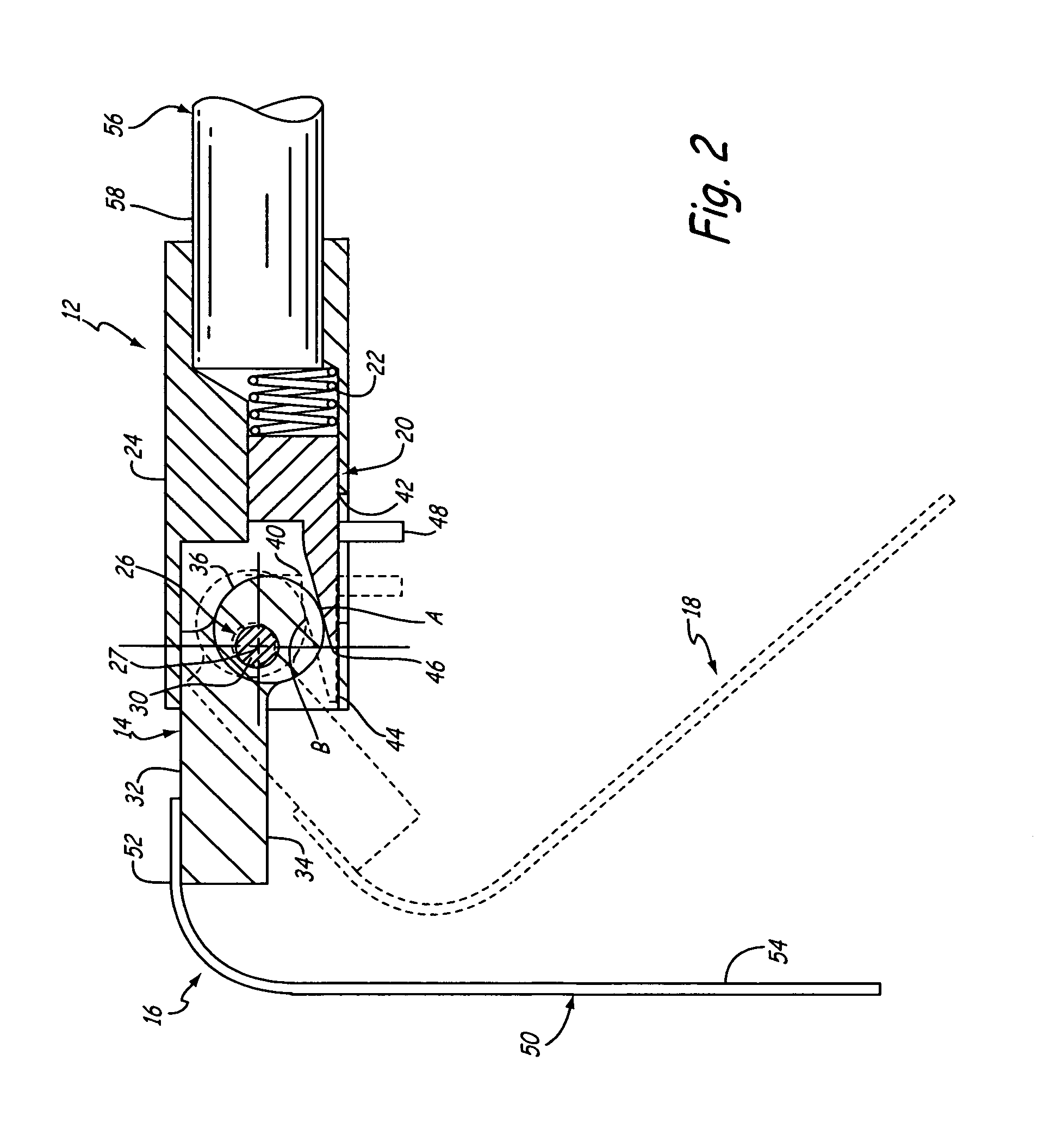
[0011]A retractor apparatus of the present invention is generally indicated at 10 in FIG. 1. A locking mechanism of the present invention is generally indicated at 12. The locking mechanism 12 is designed to automatically permit rotational movement of a retractor blade 50 in one direction only, from a first upright position 16 to a second downward position 18 (shown in broken lines), while the locking mechanism 12 is engaged. The locking mechanism 12 includes a cammed member 14, a wedge member 20, and a spring 22, all enclosed within a housing 24 as illustrated in FIG. 2.

[0012]The cammed member 14 includes a through-bore 26, the through-bore 26 defining an axis of rotation 27 for the cammed member 14. The housing 24 includes first and second mating apertures 28, only one of which is illustrated. The mating apertures 28 are aligned with each other by being positioned on opposing wall sections. The cammed member 14 is positioned within the housing 24 such that the through-bore 26 alig...


PUM


Abstract

The present invention is a mechanism for releasing a positioning device from a locked position. The positioning device has a moveable wedge urged against a rotatable cammed member which permits rotatable travel of the cammed member in only one direction. The releasing mechanism comprises a lever attached to the wedge and engageable with the cammed member. Engaging the lever with the cammed member urges the wedge away from the cammed member to permit rotation of the cammed member in either direction.

Description

CROSS-REFERENCE TO RELATED APPLICATION(S)[0001]This application is a continuation-in-part of U.S. application Ser. No. 09 / 864,681 filed on May 24, 2001, now U.S. Pat. No. 6,572,540.BACKGROUND OF THE INVENTION[0002]The present invention relates to a locking mechanism. In particular, the present invention relates to a cam and wedge locking mechanism to selectively position a surgical retractor blade attached to a retractor mounting apparatus.[0003]During many types of surgical procedures it is necessary to use a retractor to hold back tissue proximate a surgical incision. The retractor enables a surgeon to work at and in the surgical incision. Retractors typically include a blade and an arm, such as a shaft, to which the blade is attached. The retractor is generally held in place by attachment to a retractor support apparatus that is positioned over a support surface, such as an operating table. The retractor support apparatus is usually attached to a side rail located along one or mo...

Claims


Application Information

Patent Timeline
Patent Type & Authority Patents(United States)
IPC IPC(8): A61B1/32A61B17/00A61B17/02A61B17/28A61DE05C3/06E05C3/16F16B2/14F16H53/00F16H53/06
CPCA61B17/02F16C3/22F16C3/28A61B17/0206A61B2017/2927A61B2017/293A61B2017/2933F16C2316/10
Inventor DOBROVOLNY, WALTER J.
Owner MINNESOTA SCI
Why Eureka
Try Eureka