Fixation system for bones

Inactive Publication Date: 2005-12-13
WOLTER DIETMAR
View PDF13 Cites 217 Cited by
  • Summary
  • Abstract
  • Description
  • Claims
  • Application Information

AI Technical Summary

Benefits of technology

[0014]The invention relies on the surprising finding that the there are optimal positions of the bone screws depending on the bone region in order to make the anchoring of the force support, which can particularly be an implant, as favourable as possible in the bone. First and foremost, the positions concerned are those in which the bone screws would exhibit an oblique orientation to the force support or to that portion of the force support which substantially extends in parallel with the bone or bone region in which the bone screw is desired to be anchored. Therefore, the fixation system for bones having a force support with holes and with bone screws adapted to be inserted into the holes have at least one hole which is oriented obliquely to the force support. This means that the hole has a hole axis which is obliquely oriented at least to that portion of the force support

Problems solved by technology

However, if the patient loads the implant with too much of his body weight too early, which is contrary to a doctor's advice, the implant might be spoiled by bending or the implant might break.
It has been observed that if b

Method used


Image

  • Fixation system for bones
  • Fixation system for bones
  • Fixation system for bones

Examples


Example

[0034]While this invention may be embodied in many different forms, there are described in detail herein a specific preferred embodiment of the invention. This description is an exemplification of the principles of the invention and is not intended to limit the invention to the particular embodiment illustrated.

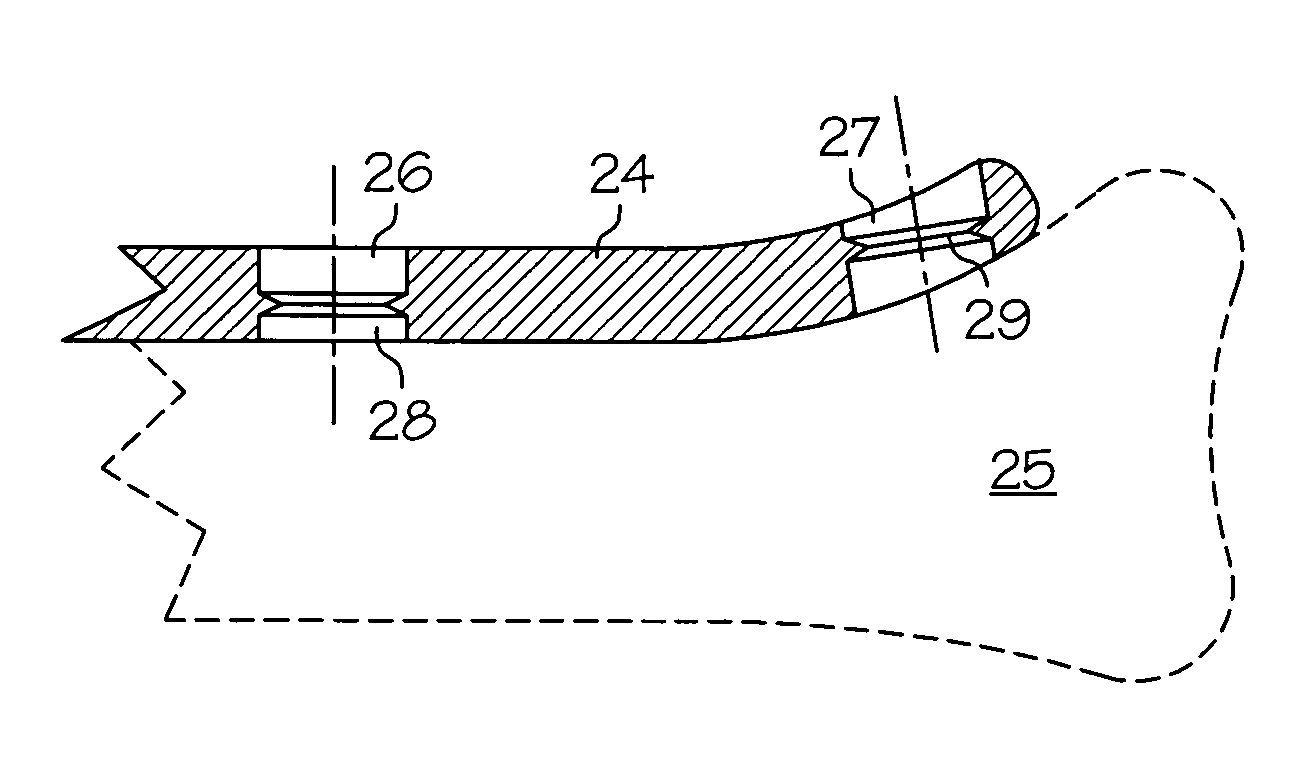
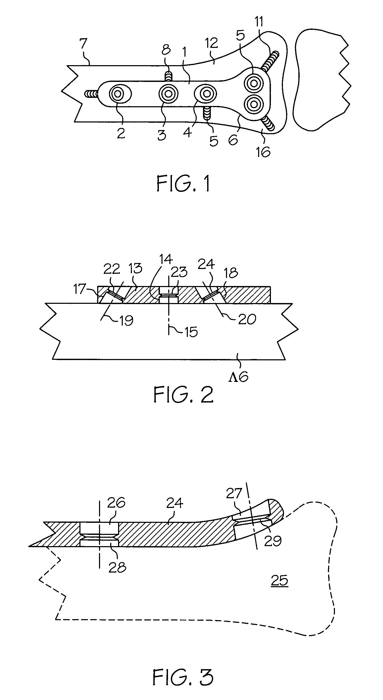
[0035]According to FIG. 1, a substantially T-shaped bone plate 1 substantially has three holes 2, 3, 4 in the elongate portion and has two more holes 5, 6 in a short, transversely oriented portion. The holes 2 to 6 have a hole axis each which is disposed obliquely to that portion of the bone plate 1 in which the respective hole 2 to 6 is located. If a bone plate 1 is completely level each hole 2 to 6 has a certain oblique orientation to the plane through the entire bone plate 1.

[0036]The holes 2 to 6 has inserted therein bone screws 7, 8, 9, 10, 11 the orientation of which matches to the orientations of the holes 2 to 6. This optimally orients the bone screws 7 to 11 to those...


PUM


Abstract

A fixation system for bones with a force support having holes and bone screws adapted to be inserted into the holes where at least one hole is oriented obliquely to the force support.

Description

CROSS-REFERENCE TO RELATED APPLICATIONS[0001]Not ApplicableSTATEMENT REGARDING FEDERALLY SPONSORED RESEARCH[0002]Not ApplicableBACKGROUND OF INVENTION[0003]The invention relates to a fixation system for bones with a force support having holes and bone screws which are insertable into the holes.[0004]If fragments of broken bones have to be joined to each other plate, nail and fixateur systems are available nowadays. Stability in plate and nail systems has been reached hitherto by the fact that if osteosynthetic plates were used bone screws firmly pulled these plates up to the bones in order to achieve a stabilization of the fragments of broken bones by means of the contact pressure which the plate exerts on the bones. If a marrow nail is used which is in the marrow space stability will also be increased by transversely inserting screws through the bone and the marrow nail. Although these screws are located in the bone by a thread minor motions are possible because the screw passes th...

Claims


Application Information

Patent Timeline
IPC IPC(8): A61B17/80
CPCA61B17/80A61B17/8052A61B17/8057A61B17/8085
Inventor WOLTER, DIETMAR
Owner WOLTER DIETMAR
Why Eureka
Try Eureka