
Card supplying mechanism and card supplying method

Active Publication Date: 2006-03-30
NISCA KK
View PDF4 Cites 19 Cited by
  • Summary
  • Abstract
  • Description
  • Claims
  • Application Information

AI Technical Summary

Benefits of technology

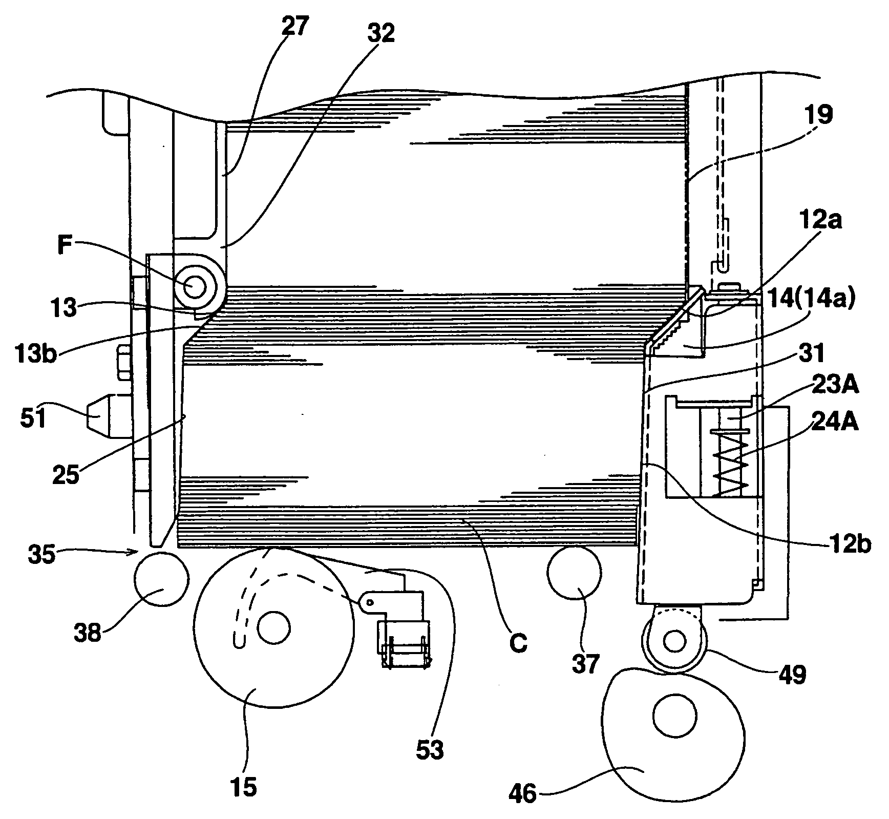
[0009] According to the first aspect of the present invention, the moving member is disposed as a single body, or as a separate body, to the support means for moving one side of a quantity of the cards stored in the card storage unit. A drive unit raises and lowers the moving member. The rising and lowering action of the moving member causes cards to drop, thereby facilitating their separation. The support means for supporting one side of cards at a predetermined height position of the card storage unit, and the aligning means for aligning another other side of the cards, reduce the load acting on the bottommost card because the entire load of stacked cards stored in the card storage unit is not applied to the bottommost card. Therefore, the kicking means is able to securely kick out a bottommost card sequentially one at a time.

Problems solved by technology

However, such cards have a tendency to stick together when the apparatus is employed in an environment having high humidity.

Method used


Image

  • Card supplying mechanism and card supplying method
  • Card supplying mechanism and card supplying method
  • Card supplying mechanism and card supplying method

Examples


Embodiment Construction

[0029] The following is a detailed description of a first embodiment that applies the invention to a printing apparatus for printing characters and / or images to a card recording medium (hereinafter referred to simply as a “card”), with reference to the drawings provided.

Main Mechanism

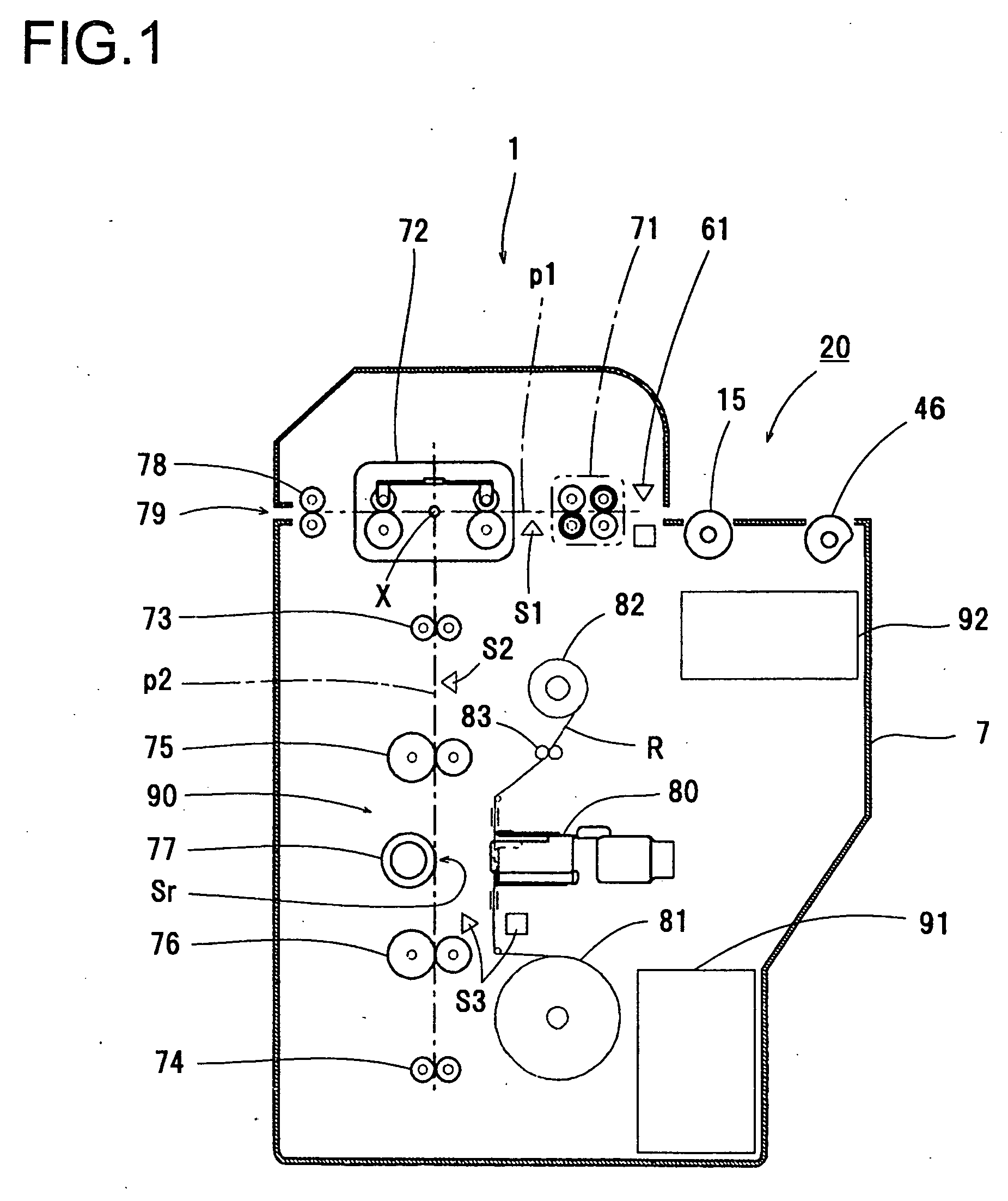
[0030] As is shown in FIG. 1, a printing apparatus 1 of the first embodiment has a first transport path p1 disposed horizontally in a plastic casing 7 for transferring cards, and a second transport path p2 disposed substantially vertically at a right angle to the first transport path p1.

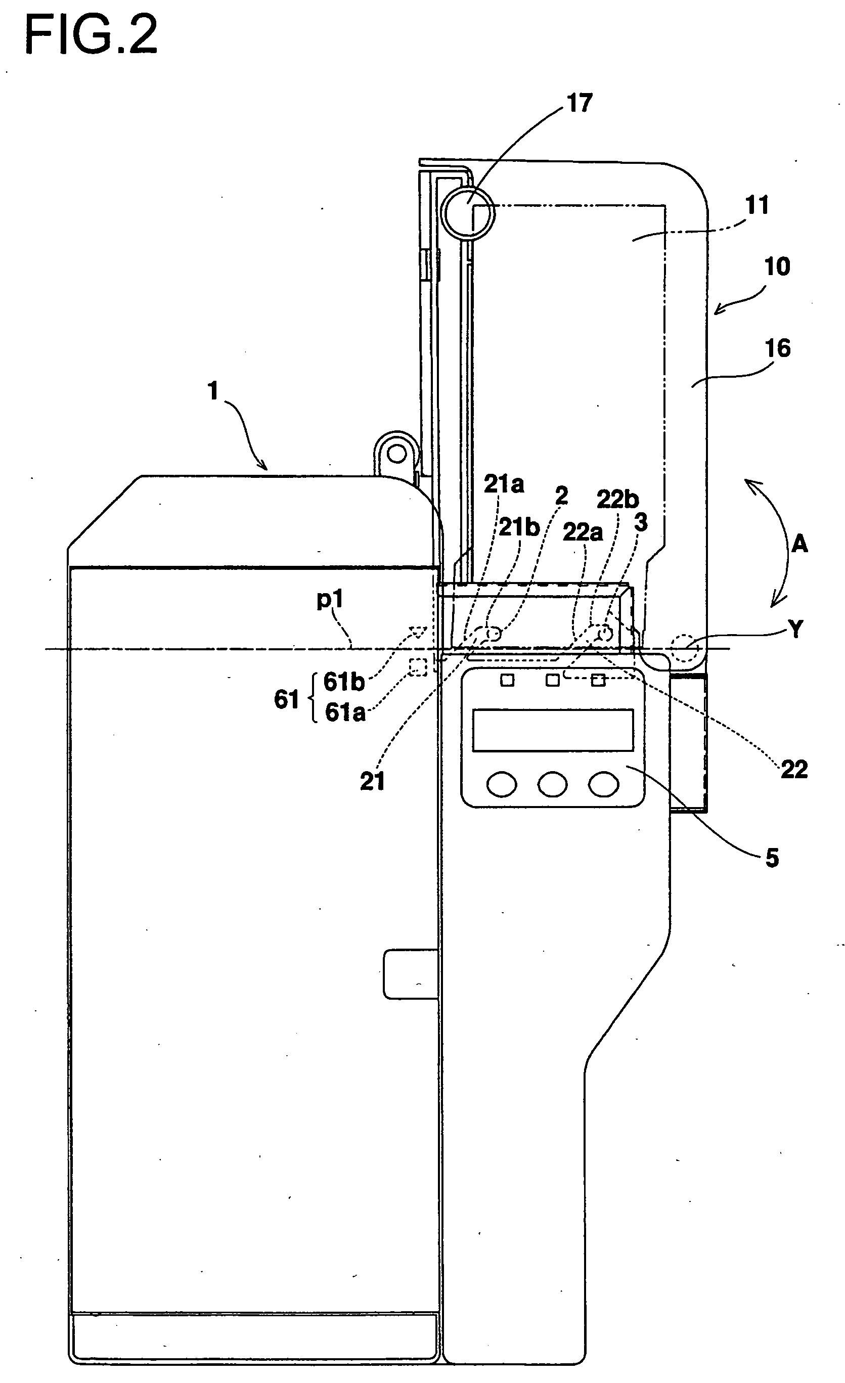
[0031] The first transport path p1 has a card supplying mechanism 10 (see FIG. 2) for kicking out one card at a time to the first transport path p1, as described below; a cleaner 71 disposed at a downstream side of the card supplying mechanism 10 for cleaning both surfaces of a card kicked out to the first transport path p1; a card turnover unit 72 that turns around an intersection point X of the first transport path...


PUM


Abstract

A card supplying mechanism includes a card stacker with a motor-driven rotatable eccentric cam for sequentially raising and lowering a moving member having an oblique, step-shaped card touching surface. A motor rotates the cam to a position of maximum diameter, thereby lifting vertically-stacked cards with the oblique, step-shaped card touching surface. The motor then drives further to rotate the cam to a position of minimum diameter, thereby separating one end of the cards on an oblique card support surface so as to mutually offset stacked cards. A kick roller then discharges from the stacker a bottommost stacked card. The card supplying mechanism provides a reliable supply of cards by virtue of both improved card separation, and reduced load on the bottommost card that is to be supplied.

Description

BACKGROUND OF THE INVENTION AND RELATED ART STATEMENT [0001] The present invention relates to a card supplying mechanism and card supplying method for supplying cards to a main unit of a card issuing apparatus or a card printing apparatus. More particularly, the present invention relates to a card supplying mechanism and card supplying method adapted to the main unit for issuing and / or printing to many cards at one time. [0002] Conventionally, to create card media, such as credit cards, cash cards, license cards, and ID cards, a thermal transfer type printing apparatus has been used for thermally transferring desired images and / or characters to cards via a thermal transfer film using a thermal transfer head. An example of a card printing apparatus that uses such a thermal transfer method is disclosed in Japanese Patent No. 3330355. [0003] Recently, because of the increased need for issuing cards by printing large volumes of cards at a time, technologies have been developed for suppl...

Claims


Application Information

Patent Timeline
IPC IPC(8): G06F7/08G06K13/00
CPCG06K13/103
Inventor TSURUTA, WATARU
Owner NISCA KK
Learn More